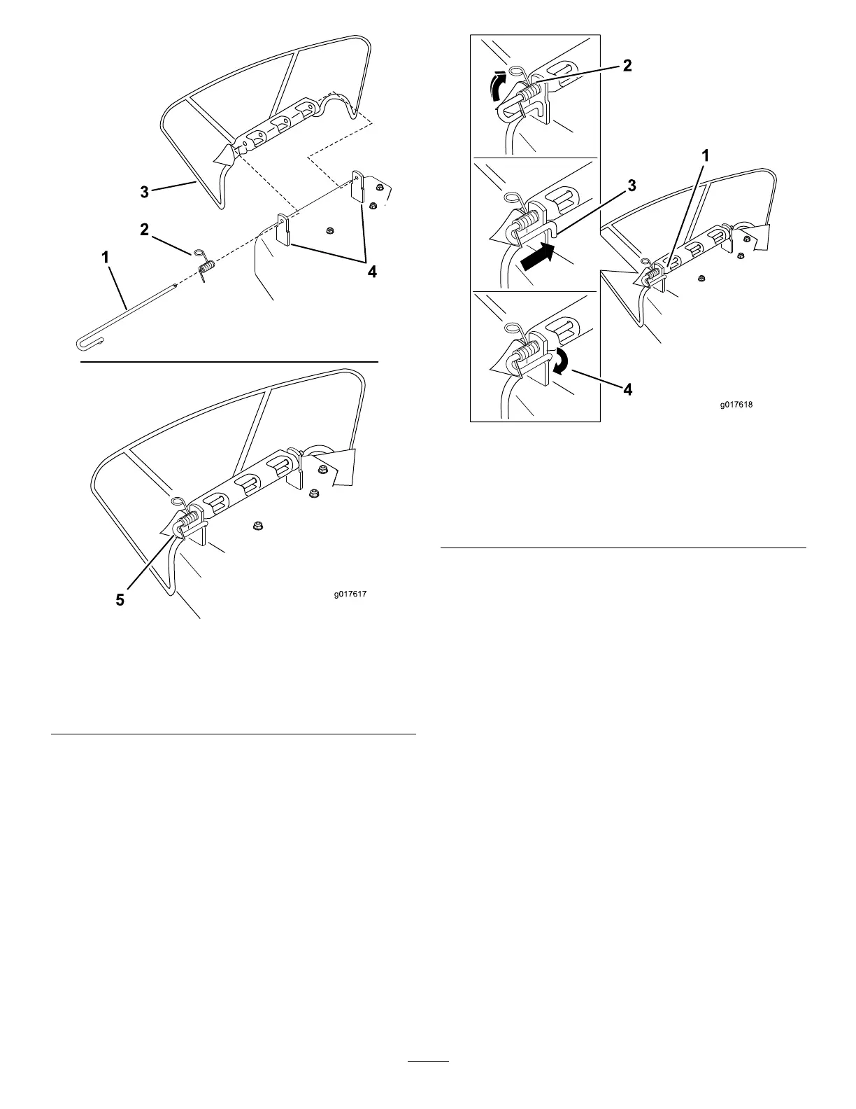
g017617
Figure 63
1. Rod 4. Deck brackets
2. Spring 5. Spring installed over the
rod
3. Deector
2. Remove the damaged or worn discharge deector.
3. Position the new discharge deector with the bracket
ends between the welded brackets on the deck as
shown in Figure 64.
4. Install the spring onto the straight end of the rod.
5. Position the spring on the rod as shown in Figure 62 so
that the shorter spring end comes from under the rod
before the bend and going over the rod as it returns
from the bend.
6. Lift the loop end of the spring and place it into the
notch on the deector bracket (Figure 64).
g017618
Figure 64
1. Rod and spring assembly
installed
3. Rod, short end, moved
behind the mower bracket
2. Loop end of the spring
installed into the notch in
the deector bracket
4. Short end, retained by
mower bracket.
7. Secure the rod and spring assembly by twisting it so
that the short end of the rod is behind the front bracket
welded to the deck (Figure 64).
Important: The grass deector must be spring
loaded in the down position. Lift the deector up
to test that it snaps to the full down position.
45