Greensmaster 1000/1600 Traction and Reel Drive SystemsPage 4 – 31
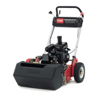
6. Use 9/16–inch open end wrench to hold the power
shaft while backing off the lock nut with a 7/8–inch sock-
et (Fig. 53).
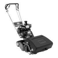
7. Remove nut from the short axle of the differential as
follows (Fig. 54):
A. Loosen small hose clamp securing the differen-
tial boot to the bearing housing.
B. Use drift punch in the hole of the short axle while
removing the nut with a 7/8–inch socket.
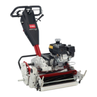
8. Remove belts from both drum drive assemblies as
follows (Fig. 55):
A. Loosen the lower carriage bolts and lock nuts se-
curing the idler brackets to the frame.
B. Remove upper carriage bolts and lock nuts se-
curing the idler brackets to the frame.
C. Swing both idler pulleys forward. Remove belts.
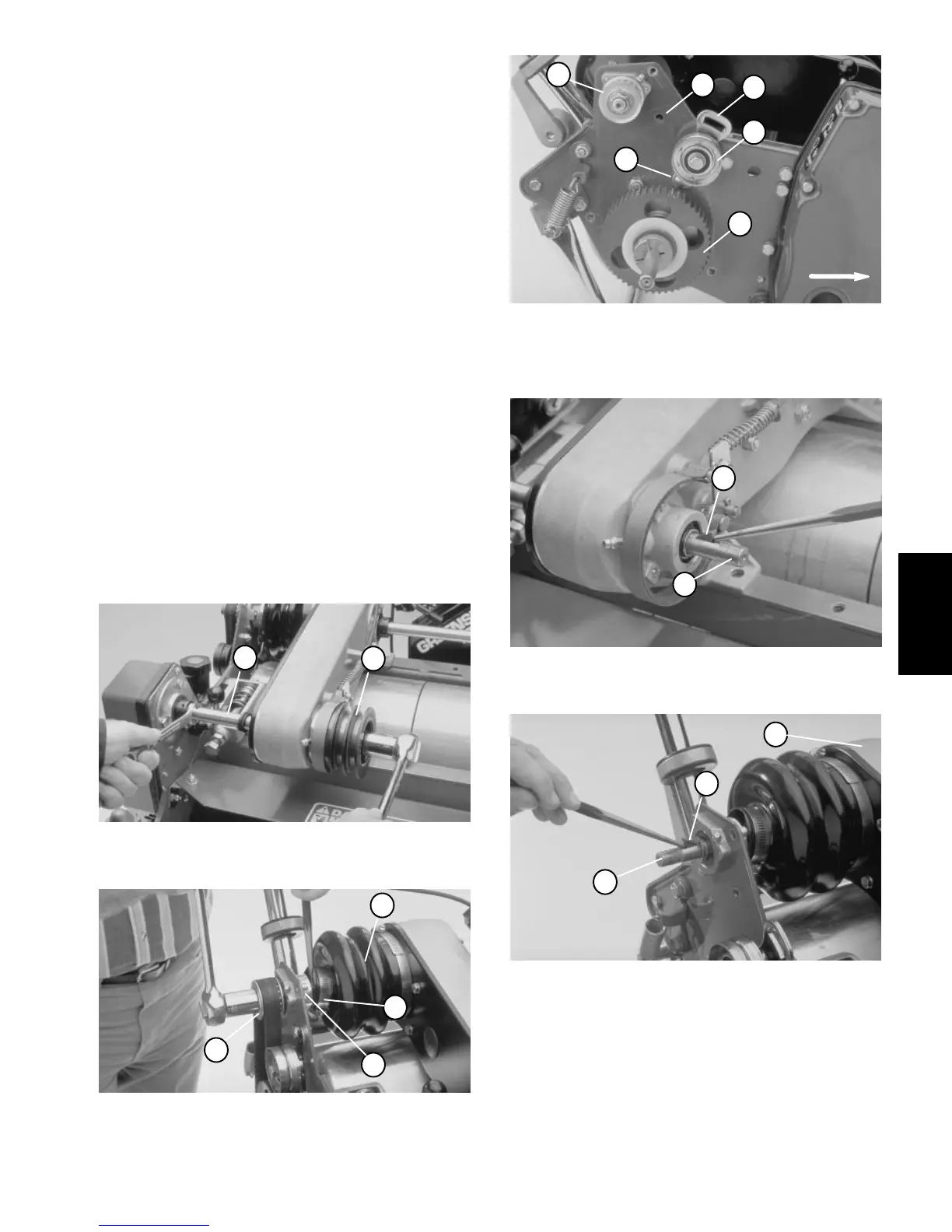
9. Remove shaft input pulley from the power shaft. Re-
move key from shaft with drift punch (Fig. 56).
10. Slide pulley off the short axle on the right side of the
countershaft housing. Remove key from the axle with a
drift punch (Fig. 57).
1. Power shaft 2. Shaft Input pulley
Figure 53
1
2
1. Small hose clamp
2. Differential boot
3. Bearing housing
4. Pulley
Figure 54
1
2
3
4
1. Carriage bolt (Lower)
2. Carriage bolt hole (Upper)
3. Idler bracket
4. Idler pulley
5. Drum shaft pulley
6. Pulley
Figure 55
1
2
4
FORWARD
5
6
3
1. Power shaft 2. Key
Figure 56
2
1
1. Axle (Short)
2. Countershaft housing
3. Key
Figure 57
3
1
2
Traction and Reel
Drive System