2.Locatetheround,multi-pinconsolecomputer
connectorsonthemainharnesssecuredtotheright
framememberunderthedashboard.
3.Cuttheplastictiethatsecurestheconsolecomputer
wiringtotheframeunderthedashboard.
4.Removethe2protectivecapsfromthecableends.
5.Routetheconsolecomputercablesfromunderthe
dashboardthroughtheholewiththelargegrommet.
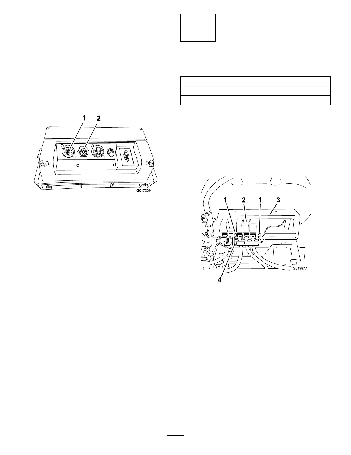
6.Plugthecablesintotheircorrespondinginputson
therearoftheconsolecomputer(
Figure3),and
securethecablesbyrotatingthelockingrings.
Figure3
RearofConsoleComputer
1.Flowmetercable
connection
2.Speedsensorcable
connection
7.Assemblethecomputerconsoletothepivotbracket
with2handknobs(Figure2).
8.Securethepivotbrackettothemountedbracketwith
2carriagebolts(5/16x3/4inch)and2locknuts
(5/16inch)asshownin
Figure2.
Note:Fingertightenthefastenersatthistime.
9.Swingtheconsoleassemblyonthebottommounting
bracketuntilitfacesthedesiredposition.
10.Tightenthefastenersthatyouinstalledpreviously.
11.Adjustthepivotangleoftheconsolefacetothe
desiredposition,andtightenthehandknobson
eithersideconsoletosecuretheposition.
2
InstallingtheFlowmeter
Partsneededforthisprocedure:
1Flowmeter
1
Gasket
1Hoseclamp,wormscrew
Procedure
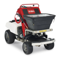
Movetotherearofthemachineandlocatetheboom
valveassemblyontheboomvalvemountbracket.
1.Loosen,butdonotremove,theboltsthatsecure
theboomvalveassemblytothemountingbracket
(
Figure4).
Figure4
1.Bolts3.Boommount
2.Boomvalveassembly4.Wormclamp
2.Loosentheexistingwormclampthatsecuresthe
agitationvalvetotheboomvalveassembly(
Figure4).
3.Carefullymovetheboomvalveassemblyawayfrom
theagitationvalve(
Figure5).
5