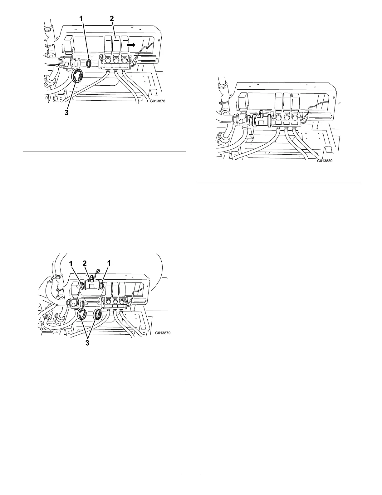
Figure5
1.Gasket
3.Wormclamp
2.Boomvalveassembly
4.Removetheexistinggasketinthevalvebody
(Figure5).
Note:Retainboththeclampandgasket.
5.Locatetheowmeter,gasket,andwormclampin
looseparts.
6.Installtheowmeterin-linebetweentheagitation
andboomvalveassemblieswiththeowarrow
pointingtowardthe3boomvalves(Figure6).
Note:Ensurethatbothgasketsareproperly
installed.
Figure6
1.Gasket
3.Wormclamps
2.Flowmeter
A.Installtheexistinggasketintotheowmeterside
thatwillmatewiththeagitationvalve(Figure6).
B.Installtheexistingwormclampoverthe
owmeter.
C.Movetheowmeterintopositionushwiththe
agitationvalvebody.
Note:Securetheowmetertotheagitation
valvebodybytighteningtheclamp.
D.Installthenewgasketintotheopensideofthe
owmeterbody.
E.Installthenewwormclampovertheopenend
oftheowmeter.
F.Carefullymovetheboomvalveassemblyintothe
positionushwiththeowmeterbody(
Figure7).
Figure7
G.Securetheowmetertotheboomvalve
assemblybytighteningtheclamp.
7.Tightentheboltsthatsecuretheboombypassvalve
assemblytothemountingbracket.
8.Locatethespraysystemwiringharnessroutedtothe
boomvalvemanifold.
9.Locatethecappedroundconnectorlabeled
owmeter.
10.Removethecaptoexposethethree-pinplugand
connectittothewirecomingfromtheowmeter.
11.Securethelockingringsifavailable.
12.Inspectallworktoensurethatallhoseclampsare
tightened.
6