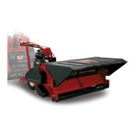
Figure21
1.Latchhandle3.Lockedposition
2.Latchhandlepininthe
unlockedposition
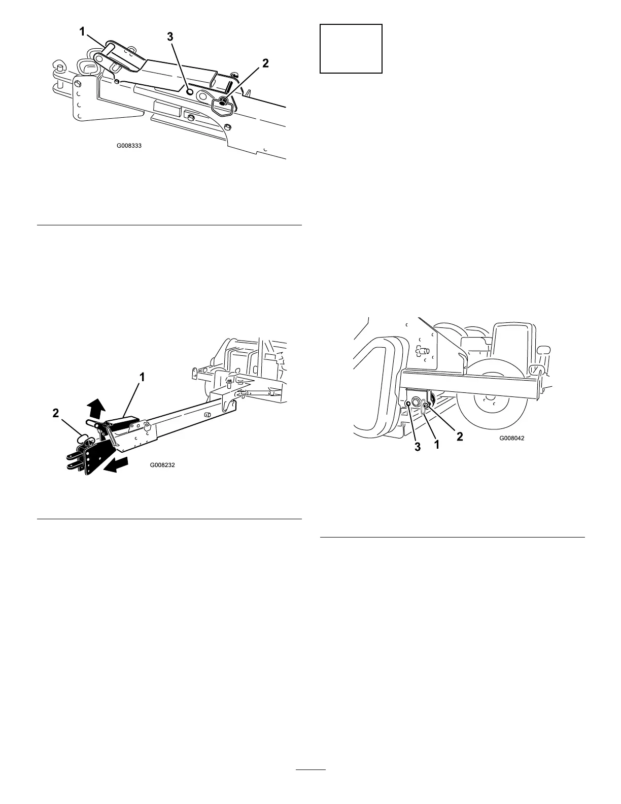
•Liftuponthelatchhandle(Figure22).
•Slowlydrivethevehicleforwarduntilthehitch
assemblylocksintoplace(Figure22).
Note:Lockthehitchassemblyintheextended
positionbymovingthelatchhandlepintothe
forward(locked)position(Figure21).
Figure22
1.Latchhandle2.Hitchassembly
9.Operatethecoreprocessorandcheckthehydraulic
uidlevelinthevehicle.Replenishasrequired.
8
DisconnectingtheCore
ProcessorfromtheWorkman
Vehicle
NoPartsRequired
Procedure
1.Removethestoragepinsfromtherearholeposition
(Figure23).
2.Slowlylowertheprocessoruntilitcomestoreston
therearrollerandtires.Installthestoragepinsinthe
frontholeposition(Figure23).
3.Afterthestoragepinsareinstalled,turnoffthe
tractor.
Figure23
1.Storagepin3.Rearhole(Coreprocessor
connectedtotowvehicle)
2.Fronthole(Coreprocessor
disconnectedfromtow
vehicle)
4.Disconnectthehydraulichoses.
5.Removetheremotecontrolfromthevehicle.
6.Windthehosesandcableontotheharnessmount
forstorage.
7.Toretractthetowhitch,liftuponthelatchhandle
andslowlybackupthevehicleuntilthehitch
assemblylocksintoplace(Figure22).
8.Lowerthejacktothegroundtostabilizethemachine
Figure24).
18