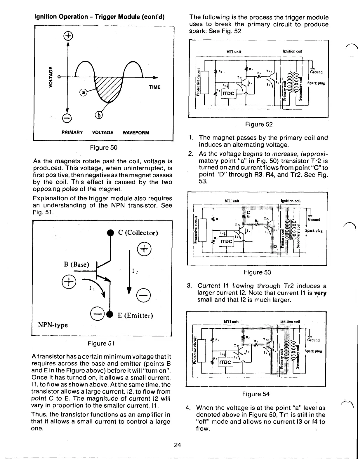
Ignition Operation Trigger Module (cont’d)
PRIMARY VOLTAGE WAVEFORM
Figure
50
As the magnets rotate past the coil, voltage is
produced. This voltage, when uninterrupted, is
first positive, then negative as the magnet passes
by the coil. This effect is caused by the two
opposing poles of the magnet.
Explanation of the trigger module also requires
an understanding of the NPN transistor. See
Fig.
51.
E (Emitter)
NPN-type
Figure
51
A
transistor has a certain minimum voltage that it
requires across the base and emitter (points
B
and
E
in the Figure above) before it will “turn on”.
Once it has turned on, it allows a small current,
l1,
to flow as shown above. At the same time, the
transistor allows a large current, l2, to flow from
point C
to
E.
The magnitude of current l2 will
vary in proportion to the smaller current,
l1,
Thus, the transistor functions as an amplifier in
that it allows a small current to control a large
one.
24
The following is the process the trigger module
uses to break the primary circuit to produce
spark: See Fig. 52
MTI
unit Ignition coil
Spark plug
Figure
52
1.
The magnet passes by the primary coil and
induces an alternating voltage.
2.
As the voltage begins to increase, (approxi-
mately point “a” in Fig.
50)
transistor Tr2 is
turned on and current flows from point
“C”
to
point
“D”
through
R3,
R4,
and Tr2. See Fig.
53.
Figure
53
3.
Current
l1
flowing through Tr2 induces a
larger current
l2,
Note that current
l1
is
very
small and that l2 is much larger.
MTI
unit Ignition coil
Figure
54
4.
When the voltage is at the point “a” level as
denoted above in Figure
50,
Trl is still in the
“off” mode and allows no current
l3
or l4 to
flow.
 Loading...