MOWER DECK
6-27
Toro Timecutter SS/MX/ZS Service Manual
6
5� Measure between the outside cutting edges and
the level surface (Fig� 126 and Fig� 127)� If both
measurements are not within 3/16” (5mm), an
adjustment is required; continue with this procedure�
6� Support deck by placing wood blocks under the
edges of the deck�
Note: Avoid placing the supports under any anti-
scalp rollers if present on the deck.
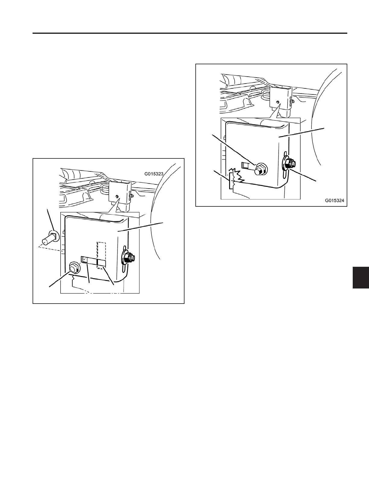
7� Move to the left side of the machine� Remove the
side carriage bolt (E) and locking nut (D) from the
xedposition.Installitintotherearslottedposition
and leave it slightly loose (Fig� 128)�
8� Loosen but do not remove, the rear locking nut on
the hanger bracket (Fig� 129)�
A� Hanger bracket C� Fixed position
B� Slotted adjustment D� Side locking nut
position E� Side carriage bolt
Fig. 128 g.49G015323
A
B
C
D
E
A� Hanger bracket C� Side locking nut
B� Rear locking nut slotted position
D� Adjustment notches
Fig. 129 g.50G015324
A
B
C
D
 Loading...