MOWER DECK
6-31
Toro Timecutter SS/MX/ZS Service Manual
6
Fig. 136 g.52G005074
6� Move to the left side of the machine� Loosen, but
do not remove, the rear locking nut on the hanger
bracket (Fig� 136)�
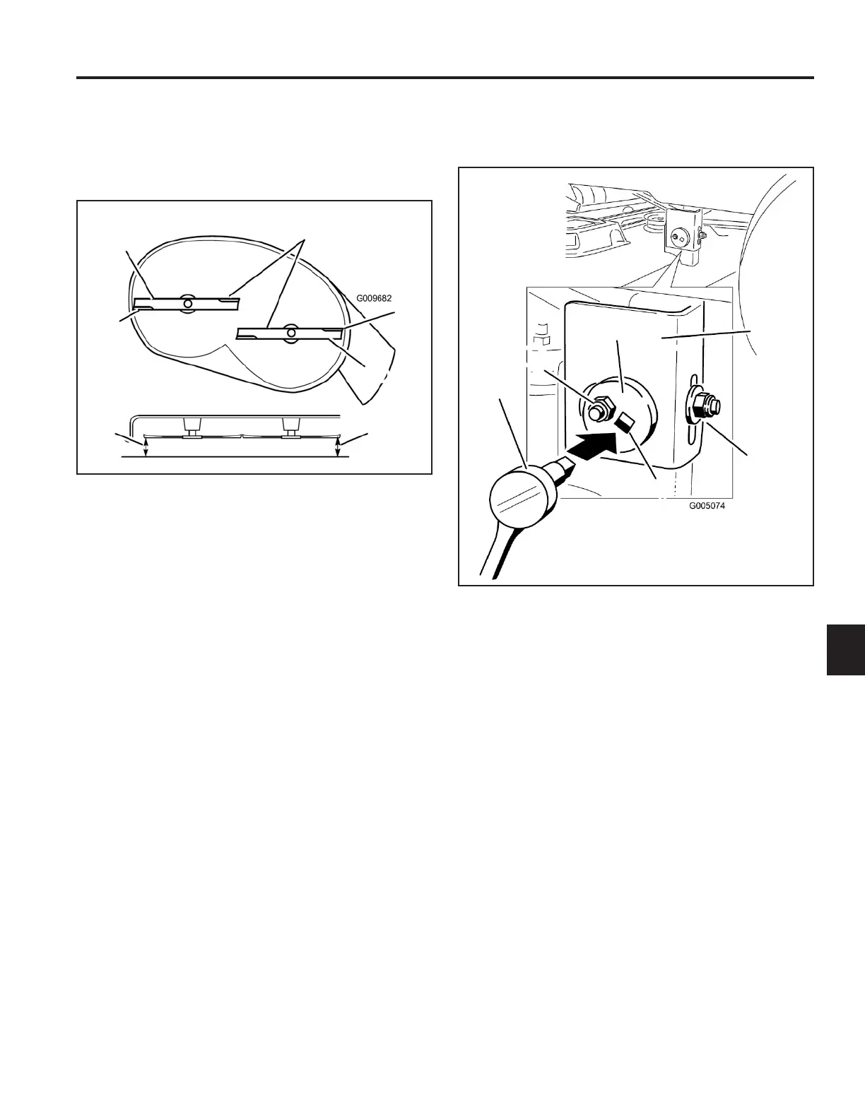
5� Carefully rotate the blades side-to-side (Fig� 135)�
Measure between the outside cutting edges and the
level surface (Fig� 135)� If both measurements are
not within 3/16” (5mm), an adjustment is required;
continue with this procedure�
Mower decks with (2) blades
A� Blades side-to-side D� Measure from blade tip
B� Sail area of blade to level surface
C� Outside cutting edges
A� Hanger bracket D� Eccentric adjustment plate
B� Rear locking nut E� Socket wrench hole
C� Side locking nut F� Socket wrench with 3/8”
extension
Fig. 135 g.51G009682
A
B
B
C
C
D D
A
B
C
D
E
F
7� Loosen the side locking nut on the hanger bracket
just enough to allow the eccentric plate to be
adjusted (Fig� 135)� Use a 3/8” drive extension on a
socket wrench to manipulate the eccentric plate� Use
the wrench to reposition the deck height and adjust
so the measurements taken in Step 5 are within
3/16” (5mm)�
8� When at the desired position, tighten the side locking
nut on the hanger bracket (Fig� 136)� Tighten the
rear locking nut on the hanger bracket�
9� Continue leveling the deck by checking the front-
to-rear blade slope; refer to “Adjusting the Front-to-
Rear Blade Slope” in this chapter�
 Loading...