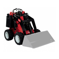
Figure11
1.Lowertheloaderarms
4.Tilttheattachmentforward
2.Raisetheloaderarms
5.Detent(Float)position
3.Tilttheattachment
rearward
Bymovingthelevertoanintermediateposition(suchas,
forwardandleft),youcanmovetheloaderarmsandtiltthe
attachmentatthesametime.
Loader-ValveLock
Theloader-valvelocksecurestheloaderarm/attachment
tiltleversothatyoucannotpushitforward.Thishelpsto
ensurethatnooneaccidentallylowerstheloaderarmsduring
maintenance.Securetheloaderarmswiththelockanytime
youneedtostopthemachinewiththeloaderarmsraised.
Tosetthelock,liftuponitsothatitclearstheholeinthe
controlpanelandswingittotheleftinfrontoftheloaderarm
lever,pushingitdownintothelockedposition(Figure12).
Figure12
1.Loader-valvelock
2.Loaderarm/attachmenttilt
lever
Loader-Control-ReferenceBar
Theloader-control-referencebarhelpsstabilizeyourhand
whileoperatingtheloaderarm/attachmenttiltlever.
Auxiliary-HydraulicsLever
Tooperateahydraulicattachmentintheforwarddirection,
rotatetheauxiliary-hydraulicsleverrearwardandpullitdown
tothereferencebar(Figure13,number1).
Tooperateahydraulicattachmentinreversedirection,rotate
thehydraulicsleverrearward,thenmoveitleftintotheupper
slot(Figure13,number2).
Ifyoureleasetheleverwhileintheforwardposition,the
leverautomaticallyreturnstotheneutralposition(Figure13,
number3).Ifitisinthereverseposition,itremainsthere
untilyoupullitoutoftheslot.
Figure13
1.Forward-owhydraulics
3.Neutral
2.Reverse-owhydraulics
Parking-BrakeLever
Tosettheparkingbrake,pushthebrakeleverforwardandto
theleftandthenpullitrearward(Figure14).
Note:Thetractionunitmayrollslightlybeforethebrakes
engageinthedrivesprocket.
Figure14
Toreleasethebrake,pushtheleverforwardandthenright,
intothenotch.
FuelGauge
Thisgaugemeasurestheamountoffuelinthefueltank.
Hydraulic-FluidTemperatureLight
Ifthehydraulicuidgetstoohot,thislightilluminatesandan
audiblealarmsounds.Ifthishappens,shutofftheengineand
allowthetractionunittocool.
14

 Loading...