EasyManuals Logo

Toshiba B-SA4T Series User Manual

Toshiba B-SA4T Series
58 pages
To Next Page IconTo Next Page
To Previous Page IconTo Previous Page
Page #3 background imageLoading...
Page #3 background image
INSTALLATION PROCEDURE FOR OPTIONAL EQUIPMENT EO15-33001A
1. Cutter Module
1- 1
INSTALLATION PROCEDURE FOR OPTIONAL
EQUIPMENT
1. Cutter Module
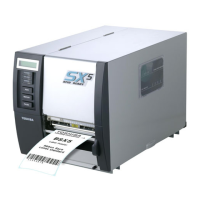
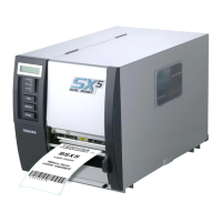
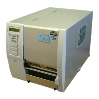
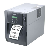
1.1 B-SA204-QM / B-SA204-QM-R
B-SA204-QM/ B-SA204-QM-R is an optional cutter module for the B-SA4TM Series (Metal cover).
Packing List
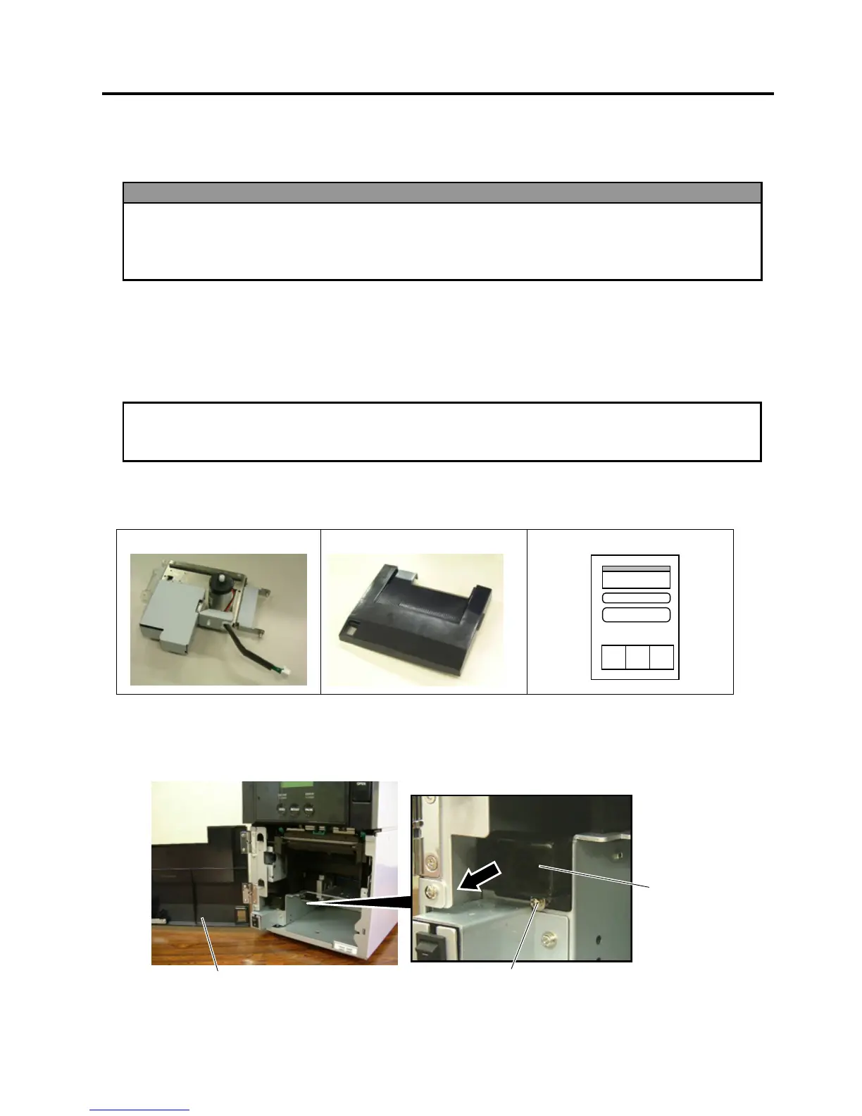
The following parts are supplied with the kit. Make sure you have all items shown below.
Cutter Unit (1 pc.)
Cutter Module Cover (1 pc.)
Installation Manual (1 copy)
Installation Procedure
1. Open the Front Cover, and remove the B-3x6 screw to detach the Connector Cover.
WARNING!
1. Turn the printer power off and disconnect the power cord before installing an optional
equipment.
2. Be careful not to pinch your fingers or hands with the covers.
3. Be careful not to injure your fingers when installing the cutter module.
CAUTION
!
Do not connect/disconnect the cutter harness to/from the printer within one minute from a power off
to
p
rotect the internal electrical circuit of the
p
rinter.
Front Cove
r
Connector Cover
B-3x6 Screw

Other manuals for Toshiba B-SA4T Series

Questions and Answers:

Question and Answer IconNeed help?

Do you have a question about the Toshiba B-SA4T Series and is the answer not in the manual?

Toshiba B-SA4T Series Specifications

General IconGeneral
Print TechnologyThermal Transfer / Direct Thermal
Print SpeedUp to 152.4 mm/sec (6 ips)
Max Print Width104 mm (4.09")
Resolution300 dpi
ConnectivityUSB 2.0
Optional InterfacesWireless LAN
BarcodesUPC/EAN/JAN, Code 39, Code 93, Code 128, EAN 128, NW7, Industrial 2 of 5, Postnet, RM4SCC, KIX-Code
2D CodesData Matrix, PDF417, QR Code, Maxi Code, Micro PDF417, Aztec Code
Media Thickness0.06 – 0.19 mm
Media Roll DiameterMax. 127 mm
Ribbon LengthUp to 300 m
Weight15 kg

Related product manuals