INSTALLATION PROCEDURE FOR OPTIONAL EQUIPMENT EO15-33001A
1. Cutter Module
1- 4
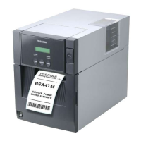
1.2 B-SA204P-QM-R
B-SA204P-QM-R is an optional cutter module for the B-SA4TP Series (Plastic cover).
• Packing List
The following parts are supplied with the kit. Make sure you have all items shown below.
Cutter Unit (1 pc.)
Cutter Module Cover (1 pc.)
Installation Manual (1 copy)
• Installation Procedure
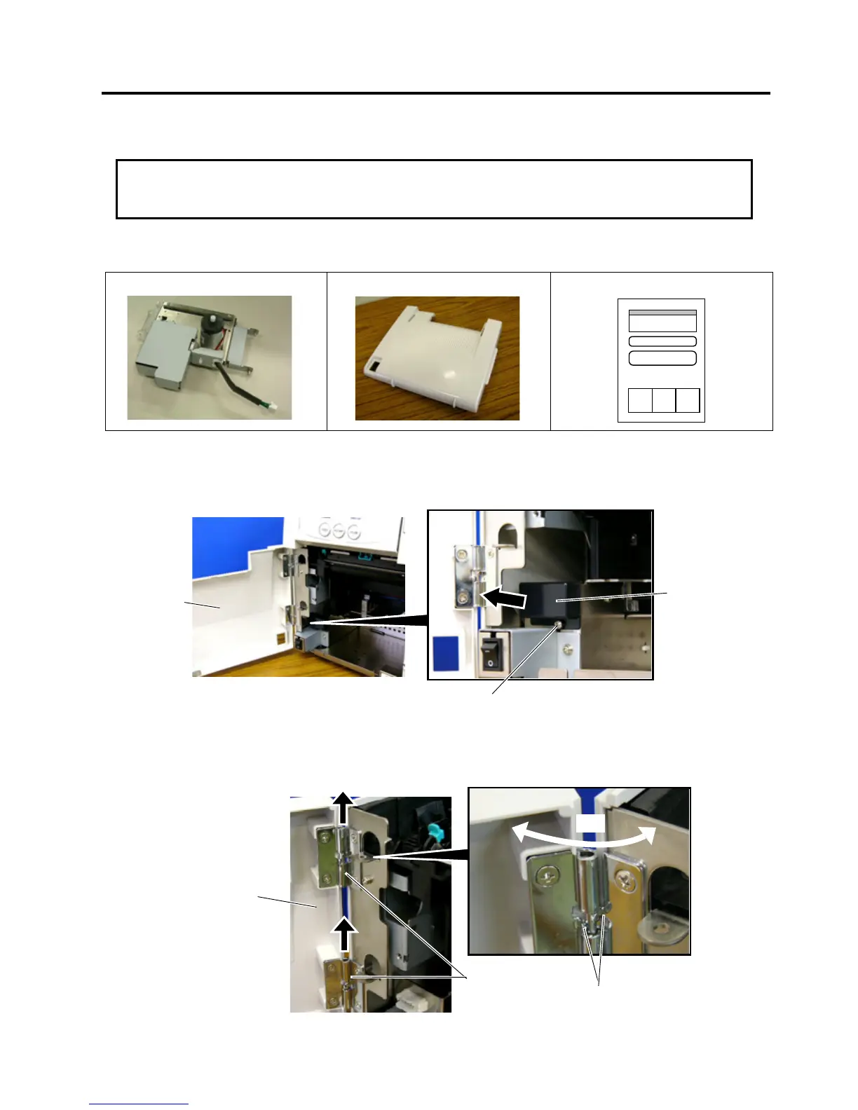
1. Open the Front Cover, and remove the Connector Cover.
2. Open the Front Cover wider. Remove the Front Cover by lifting it to disengage the hinge pins from the
hinge. The Front Cover cannot be removed unless it is opened at an angle of over 100 degrees as the
stoppers of the hinge prevent disengagement.
CAUTION
 Loading...