– 62 –
P.C.board
support
Connector
× 6 Screws
RemarksProcedure
1) Remove the back cabinet and side cabinet.
(6 screws)
1) Remove the connector. (16 portions)
2) Remove the P.C. board supports (4 portions), and
take out the P.C. board assembly.
1) Remove the capacitor band. (Each 1 screw)
2) Disconnect the lead wire from the capacitor terminal.
1) Remove the electrical parts cover. (1 screw)
2) Remove the capacitor band. (2 screws)
3) Disconnect the lead wire from the capacitor termi-
nal.
1) Remove the electrical parts cover. (1 screw)
2) Remove the transformer. (2 screws)
3) Disconnect the connector from the P.C. board
assembly.
No.
‚-1
‚-2
‚-3
‚-4
‚-5
Part name
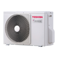
Back cabinet
Side cabinet
P.C. board
assembly
(For outdoor unit)
Capacitor for
compressor
Capacitor for fan
motor
Transformer for
outdoor unit
 Loading...