INTERFACE MANUAL
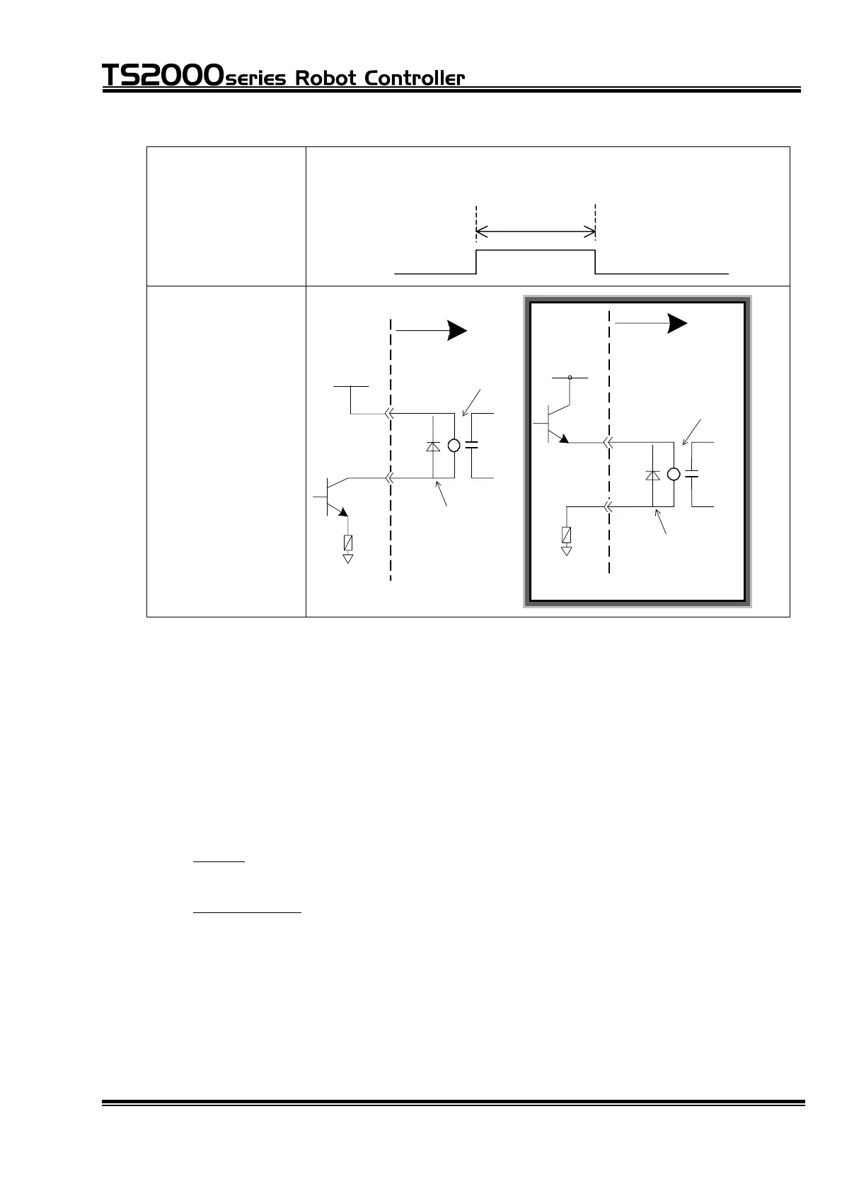
Signal timing When performing pulse output by the PULOUT command, the
output pulse width should be 200 ms or over.
DO_1~DO_32
200 ms
Example of circuit
User side
P24V
●
P24G
●
●
[ Sink type ("-" common) ]
DC relay
Counter voltage
preventing diode
User side
P24V
P24G
Counter voltage
preventing diode
●
●
DC relay
[ Source Type ("+" common) ]
●
* When using the system output signals as the digital output signals:
When "Default" (standard PLC) is specified by user parameter [U11] (I/O mode),
you can select whether OUTPUT13 ~ 16, 25 ~ 32 are the system output signals
or digital output signals.
User parameter [U14]
[U14] Select output signal (Default I/O mode only)
{Output 13 14 15 16} (0: System 1: User)
= 1 1 1 1
{Output 25 26 27 28 29 30 31 32} (0: System 1: User)
= 0 0 0 0 0 0 0 0
Specify "1" for a desired bit underlined above, and appropriate system output
signal can serve as the digital output signal. Respective bits on the upper side
signify DO_13, DO_14, BT_ALM and SV_RDY when viewed from the left, and
respective bits on the lower side represent ACK, TEACH, EXTSIG, SYS_RDY,
ALARM, AUTORUN, CYC_END and LOW_ST when seen from the left. They
correspond to digital signals DO_13 ~ DO16, DO_25 ~ DO_32, respectively.
STE 71367
– 63 –

 Loading...


