- 20 - tousek / EN_ST-63_02 / 25. 03. 2020
Safety edges connections and adjustments
G
safety edge LL1 (8,2kΩ safety edge 1, left leaf: terminals KL1 50/52) Safety edges
not active: should not be evaluated.
opening active: should be evaluated at opening.
closing active: should be evaluated at closing.
opening / closing: should be evaluated at opening and closing.
G
safety edge LL2 (8,2kΩ safety edge 2, left leaf: terminals KL1 50/53) Safety edges
not active: should not be evaluated.
opening active: should be evaluated at opening.
closing active: should be evaluated at closing.
opening / closing: should be evaluated at opening and closing.
G
safety edge RL1 (8,2kΩ safety edge 1, right leaf: terminals KL1 50/54) Safety edges
not active: should not be evaluated.
opening active: should be evaluated at opening.
closing active: should be evaluated at closing.
opening / closing: should be evaluated at opening and closing.
G
safety edge RL2 (8,2kΩ safety edge 2, right leaf: terminals KL1 50/55) Safety edges
not active: should not be evaluated.
opening active: should be evaluated at opening.
closing active: should be evaluated at closing.
opening / closing: should be evaluated at opening and closing.
status: not triggered
status: triggered
status: contact strip not connected
or defect
status: contact strip deactivated in menu
$o
$x
$
$-
e.g.
$$$$$$$$$$$$$$$$
$$$$$$$$$$$$$$$$
LL1 LL2 RL1 RL2
SE-status display Safety edges
Status dsplay of safety sensing edges LL1 left leaf (1) RL1 right leaf (1)
LL2 left leaf (2) RL2 right leaf (2)
Safety sensing edges
• OBSTACLE DETECTION: When a contact strip is triggered/activated then a change of
direction is eected for 1s. After that the gate stops.
• The safety sensing edges are activated and have the function OPEN/CLOSE by default. Tha
safety sensing edges can be deactivated or the function can be changed while the basic
settings are carried out (
see below)
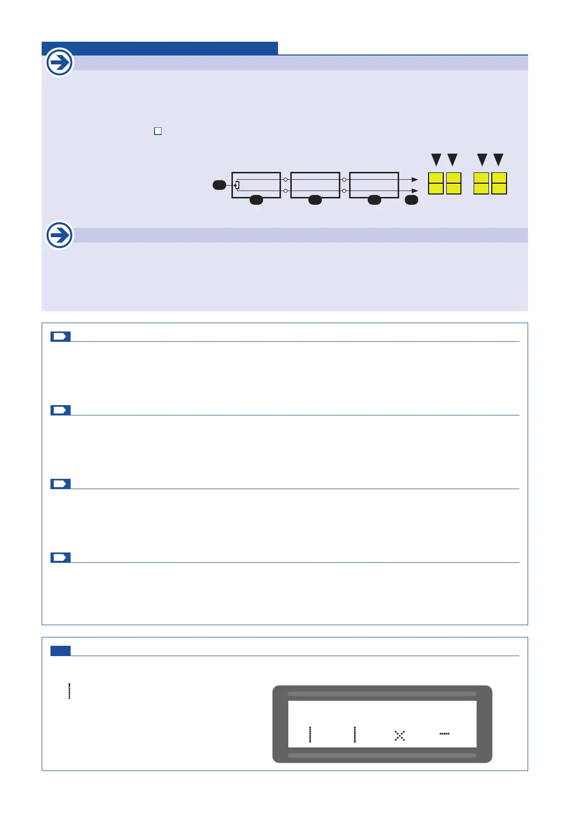
• Safety sensing edges on the same gate leaf and with the same function (i.e. active when
opening, closing or opening / closing) can be connected in series as shown below.
Example: W 8,2kΩ nal resistance
E nal edge
D passage edge
S to control When connecting one safety edge a nal edge (E) has to be used.
Important
• After giving the impulse to automatically program the end positions, no other impulse must be given. Also the
safety devices mustn´t be triggered. This would lead to an interruption of the programming process.
• Therefore, the mechanical stops must be set so that the existing contact strips cannot be triggered.
safety edge LL1
safety edge LL2
E
W
D D S
50
52
50
53
safety edge RL1
safety edge RL2
50
55
50
56
 Loading...