tousek / EN_ST-63_02 / 25. 03. 2020 - 35 -
B
K-A
TA
T
ISD
FE
F
L2 L1
For connection, adjustment and mainte-
nance works ensure that the electronics
are not damaged by moisture (rain).
With ST 63 no limit switch is
necessary: terminals 60/61 have to be
wire bridged!
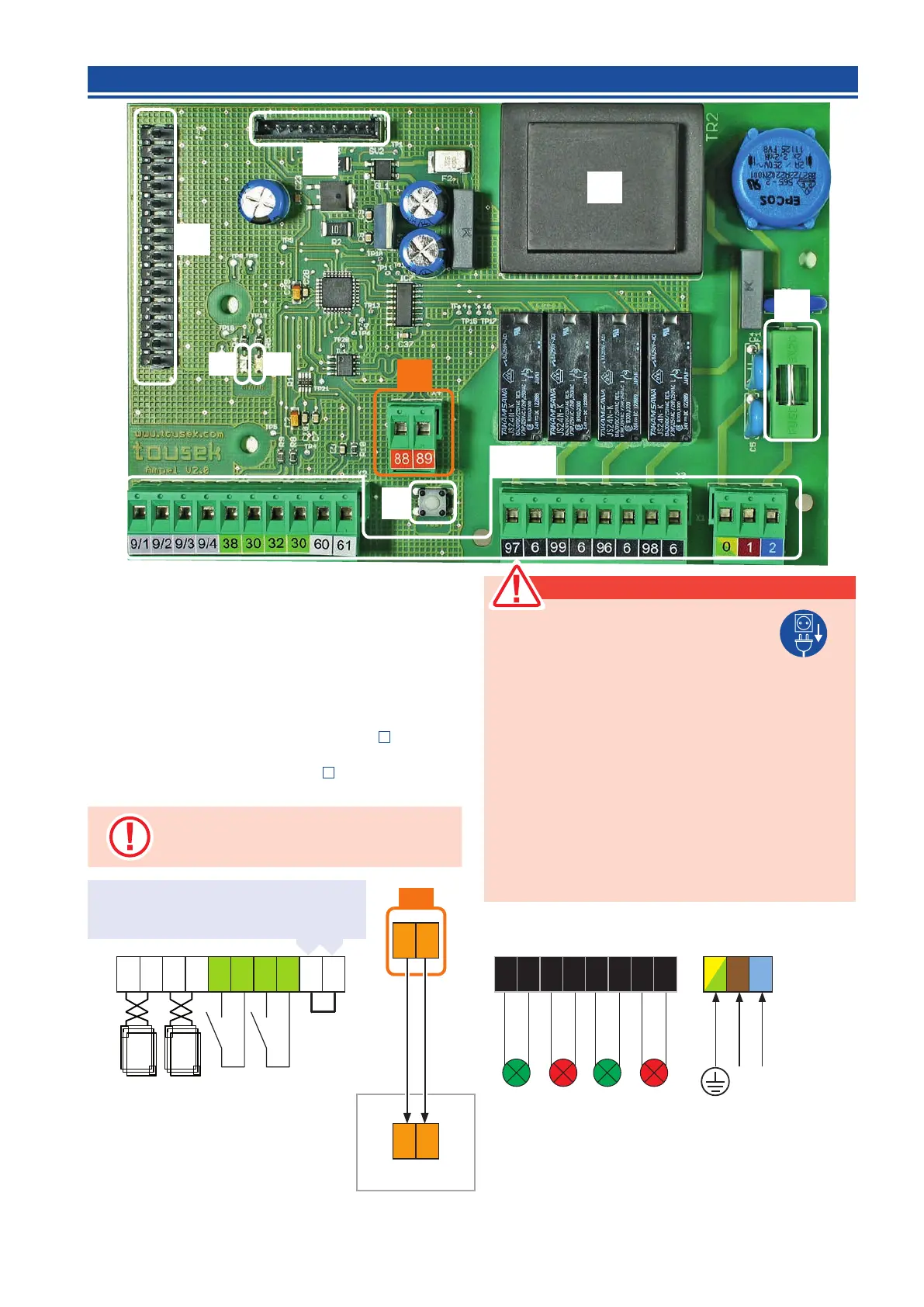
Components of trac light control board
(K-A) Terminals
(B) Bus terminals (connection with operator control unit)
(TA) Test button (switches all trac lights on)
(L 1) green LED: Status OK
(L 2) red LED: error (message on the display of the drive
control)
(T) Transformer
(ISD) Slot for optional induction loop detector
(
p. 38)
(command)
(FE) Slot for optional radio receiver (
p. 37)
(F) fuse 3,15A T
5.2 Control board overview and terminal assignment Trac light control unit STA 11
Warning
• Before opening the control housing please
switch o necessarily the main switch!
• In-supplied control inside the unit is powered.
• the safety regulations to prevent electrical shock have to
be respected.
• The unit is designed to be connected by qualied perso-
nnel.
• The device must not be used in hazardous areas!
• A pole disconnecting main switch with a min. contact gap
of 3mm has to be provided. The system must be protected
in each case in accordance with applicable safety regula-
tions!
• IMPORTANT: The control lines (buttons, radio remote
control, light barriers, etc.) have to be separated from
the 230 lines (supply, motor, signal light) to relocate
230V max. 60W
L N
earth
230Va.c.
Phase
50Hz
neutral
0
1
2
9/1
9/2
9/3
9/4
38
30
32
30
97
6
99
6
96
6
98
6
induction loop
outside
induction loop
inside
impulse switch
outside
impulse switch
inside
Limit switch
GREEN
outside
RED
outside
GREEN
inside
RED
inside
B
ST REX
Bus
High
Bus
Low
88
89
88
89
60
61
Z1