- 38 - tousek / EN_ST-63_02 / 25. 03. 2020
Mounting and installation
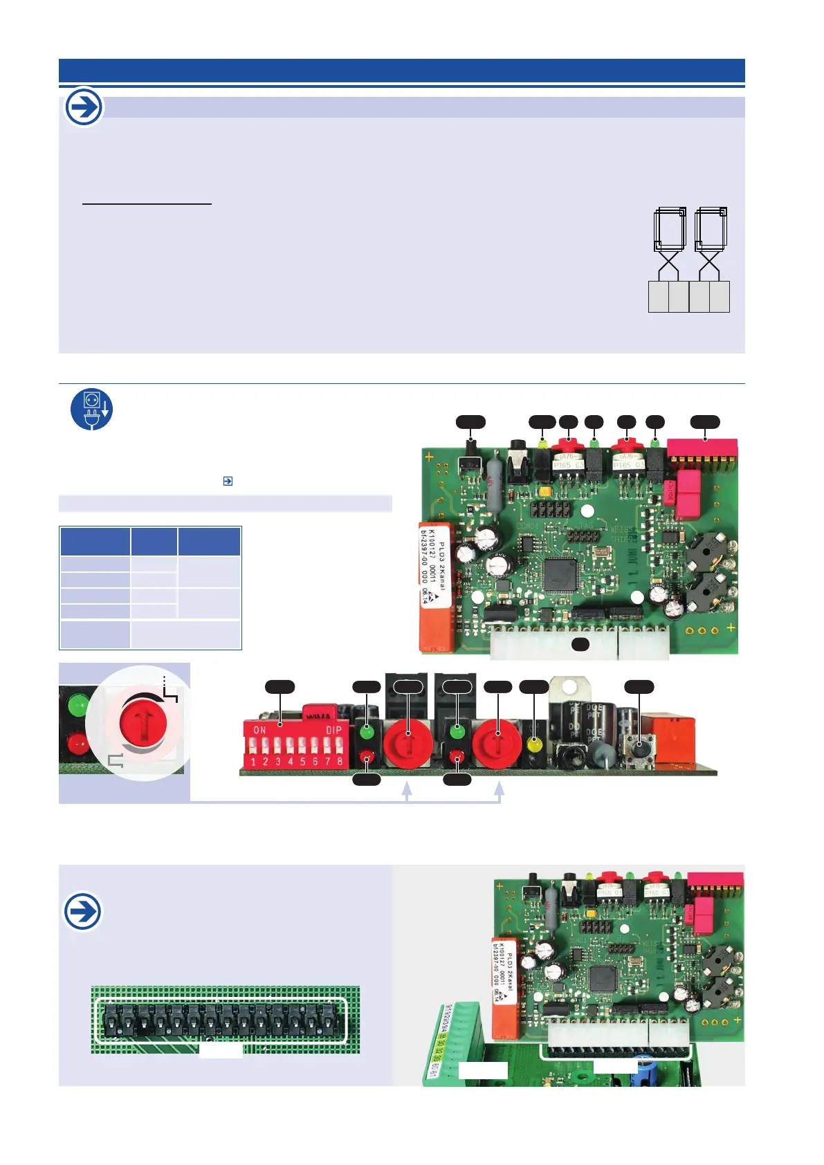
Switch o the power supply. open the control board housing and plug the I-loop detector onto the connection
slot as shown on picture.
• All detector settings can be made easily with the rotary
switches (D1) for channel 1 and (D2) for channel 2 as well
a s the DIP-switches (DIP). see corresponding manual.
Factory settings (DIP1–DIP8 = OFF, D1 and D2 = 4).
DIP DIP-switch
RES Reset-button
M Molex bar
D1 rotary switch
channel 1
D2 rotary switch
channel 2
LED´s
for
channel
display
G1 (green) 1
detection
G2 (green) 2
R1 (red) 1
defective
R2 (red) 2
PWR (yel-
low)
blinking when adju-
sting / power
RES DIPG2D2D1 G1PWR
M
15
.
1
9
.
7
412
Rotary switches D1, D2 and DIP
in factory setting
RESDIP D2 D1G2 G1 PWR
R2 R1
The Reset button (RES) has 2 functions which can be activated via the dierent duration of the key pressure:
• Adjustment: short key pressure (< 2s), Initialization of all activated loop channels.
• Reset: average duration of the key press (> 2s), reset the detector, subsequent initialization of all channels.
ISD
STA 11
Insert the board of the induction loop detector
on the slot (ISD) of the trac light control unit
STA 11.
ISD
5.5 2 channel induction loop detector ISD 6 (optional) Trac light control unit STA 11
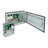
Important
• The device is for plugging onto a compact control board. The compact control board has to be built
into a separate housing with IP54-insulation.
• After each device setting a readjustment is carried out automatically. After a change in the frequency
(DIP switch 1: OFF / ON) the Reset-button (RES) has to be pressed.
• Special notes for loop: The safe function of the device depends essentially on the correct techni-
cal installation and of the laying of the loop wire, as these are the sensors of the device. The loop
should not be mechanically loaded or moved. The loop feed line has to be twisted for approx. 20
to 50 times per meter and separated from any voltage carrying lines.
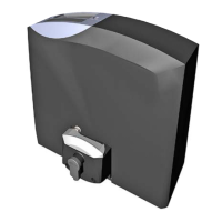
• With the 2 channel induction loop detector ISD 6 both loops can be evaluated (the green / open
request inside and outside can be realised).
•
The loop connection has to be made to terminals 9/1-9/2 (= loop 1) and 9/3-9/4 (= loop 2).
• Detailed informations can be found in the corresponding manual.
9/1
9/2
9/3
9/4
I-loop 1
I-loop 2
STA 11
 Loading...