70
ADJUSTING VALVE CLEARANCE
Shims
When servicing the valve assembly, inspect valve seats,
valve stems, valve faces, and valve stem ends for pits,
burn marks, or other signs of abnormal wear.
NOTE: All valves can be adjusted using the follow-
ing procedure with the exception of the intake and
exhaust valves nearest the drive gears (see ALTER-
NATE VALVE CLEARANCE ADJUSTMENT in this
section).
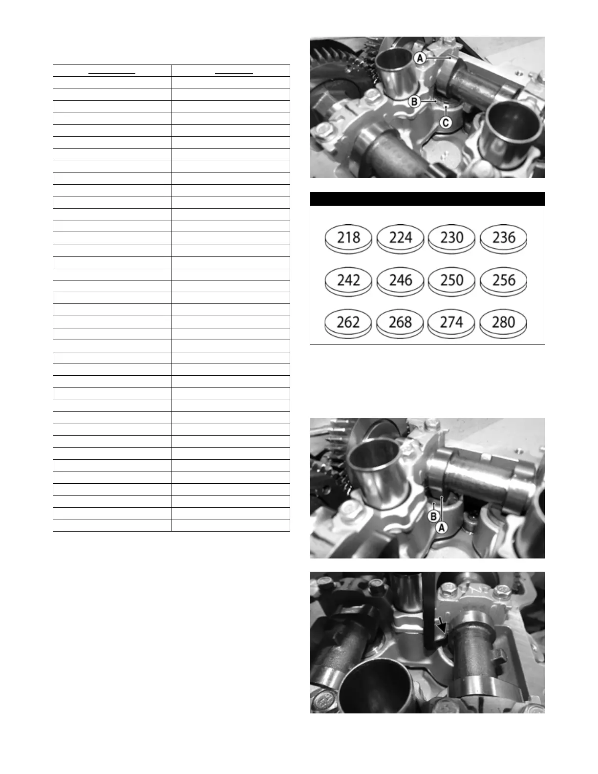
1. To adjust valve clearance, rotate the engine in the
direction of rotation until the camshaft lobe (A) high
point is directly opposite the valve bucket (B) of the
valve to be checked; then with a small pick or screw-
driver, rotate the bucket until notch (C) is accessible.
MF078B
2. Turn the crankshaft in direction of rotation until high
point (A) of the camshaft lobe of the valve to be
adjusted points directly down toward the valve
bucket (B), fully opening the valve; then insert the
Valve Adjust Tool, in position between the camshaft
and the valve bucket.
MF077A
MF074A
Part Number
Thickness
3040-157
2.06 mm
3040-158
2.08 mm
3040-159
2.10 mm
3040-160
2.12 mm
3040-161
2.14 mm
3040-162
2.16 mm
3040-163
2.18 mm
3040-164
2.20 mm
3040-165
2.22 mm
3040-166
2.24 mm
3040-167
2.26 mm
3040-168
2.28 mm
3040-169
2.30 mm
3040-170
2.32 mm
3040-171
2.34 mm
3040-172
2.36 mm
3040-173
2.38 mm
3040-174
2.40 mm
3040-175
2.42 mm
3040-176
2.44 mm
3040-177
2.46 mm
3040-178
2.48 mm
3040-179
2.50 mm
3040-180
2.52 mm
3040-181
2.54 mm
3040-182
2.56 mm
3040-183
2.58 mm
3040-184
2.60 mm
3040-185
2.62 mm
3040-186
2.64 mm
3040-187
2.66 mm
3040-188
2.68 mm
3040-189
2.70 mm
3040-190
2.72 mm
3040-191
2.74 mm
3040-192
2.76 mm
3040-193
2.78 mm
3040-194
2.80 mm
Available Valve Clearance Adjustment Shims
 Loading...