71
3. Firmly holding the bucket retainer and rotate the
crankshaft so as to position the camshaft lobe high
point away from the valve bucket; then, using a
small screwdriver and magnet, tip the valve adjust-
ment shim up and out of the valve bucket.
MF075A
4. Read the number on the valve side of the adjustment
shim placing a decimal point after the first number.
MF076
5. Verify the printed number by checking the thickness
with a micrometer or accurate calipers.
NOTE: To increase valve clearance, decrease the
shim thickness. To decrease valve clearance, increase
the shim thickness.
Calculating Shim to Install
To calculate the desired shim to install, proceed as fol-
lows:
1. Add the thickness of the removed shim to the mea-
sured valve clearance; then subtract the desired
valve clearance to find the shim value required.
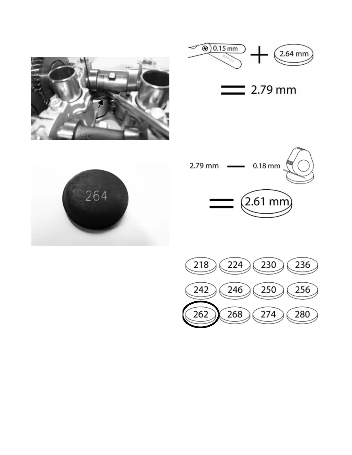
2. Example: Measured valve clearance on an intake
valve was 0.15 mm and the removed shim was
2.64 mm. Adding 0.15 mm to 2.64 mm, we get a
value of 2.79 mm.
MF076B
3. Subtracting the desired intake valve clearance of
0.18 mm from 2.79 mm, will result in a shim value
of 2.61 mm.
MF076C
4. Choose the shim size closest to the calculated shim
value — in this case, 2.62 mm (262).
MF076D
5. Install the new shim with the number side down,
making sure it is properly seated in the valve bucket:
then rotate the crankshaft until the high point is
directed downward toward the valve.