Installation - Mechanical
CLCH-SVX009J-EN 37
14. The duct extensions do not extend as far and do not
reach the cabinet panel. The gap is bridged by a flexible
foam gasket. Contact Service Parts for angle/gasket ki
15. Reattach front/back panels.
16. Reattach access doors and side panels.
17. Reattach roof.
18. Reattach coil to roof support.
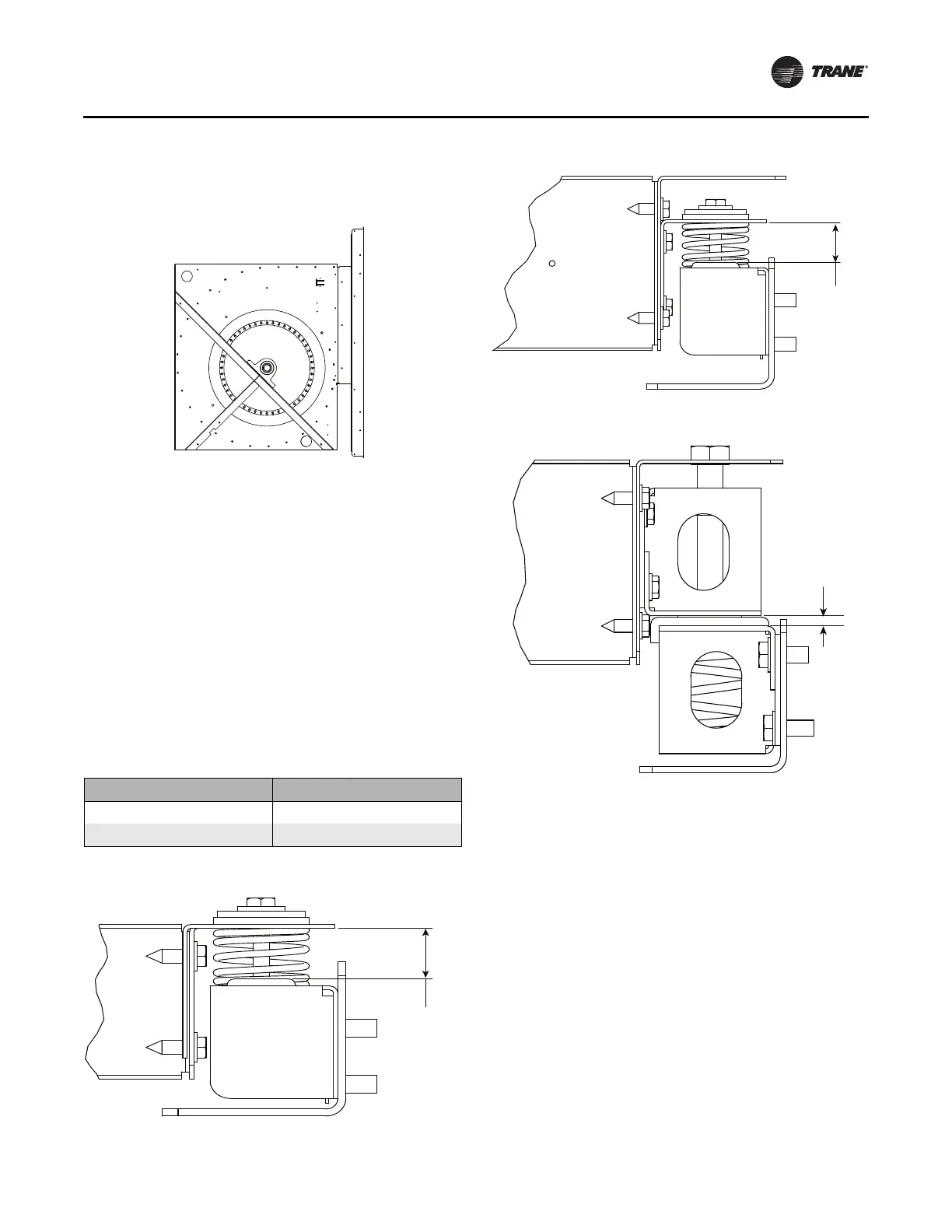
Adjusting the Isolators
Once the shipping tie-downs are removed and the internal
isolation is released on FC fans only, it may be necessary
to adjust the isolators to achieve the proper operation
height of the fan and motor isolation base. Minimum
required clearances are listed in Table 7. To determine the
isolator clearances on all unit sizes, measure between the
top of the cabinet channel and the bottom of the isolation
base channel. See Figure 42, Figure 43, and Figure 44.
Figure 41. Contact service parts for angle/gasket kit
Table 7. Minimum isolator clearance
Unit size Required Clearance
3-10 1 in.
12-30 3/8 in.
Figure 42. Isolator adjustment for sizes 3-8
Figure 43. Isolator adjustment for unit size 10
Figure 44. Isolator adjustment for unit size 12-30
Required
clearance