Coil Piping and Connections
CLCH-SVX009J-EN 41
Water Coil Piping
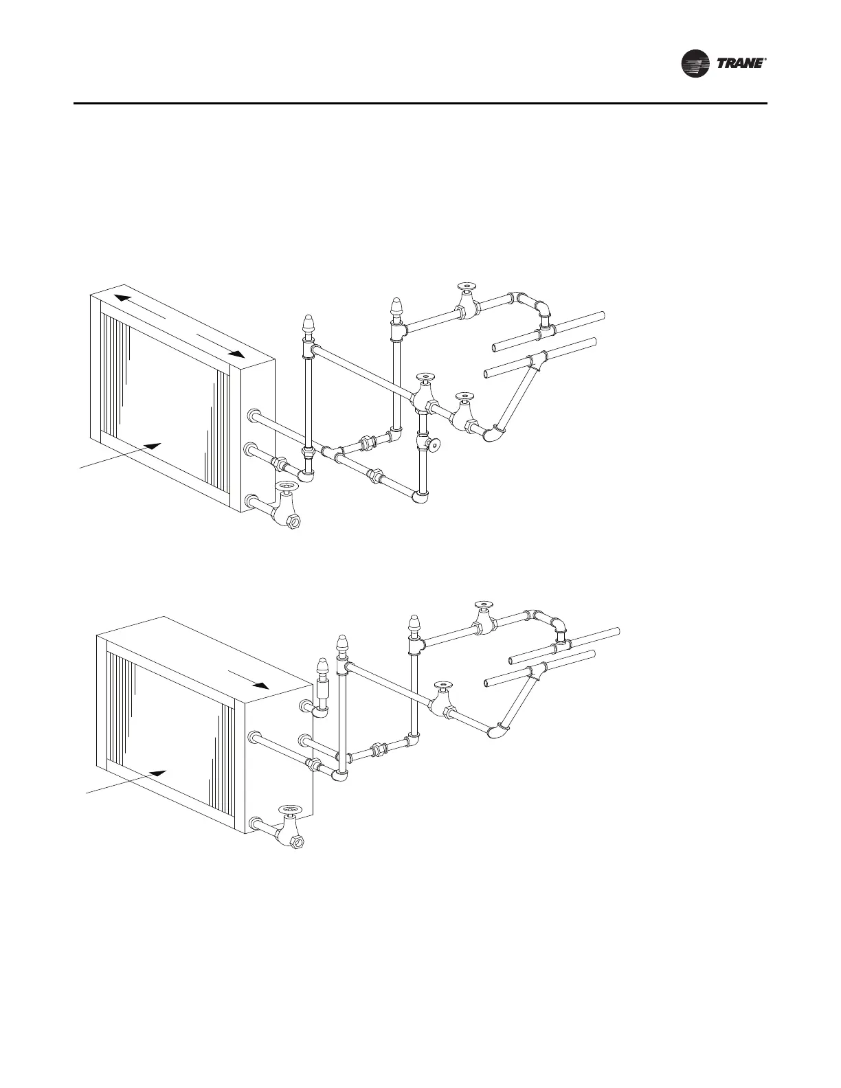
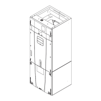
Figure 47 and Figure 48 illustrate typical water coil piping
configurations.
Water coils are self-venting only if the water velocity
exceeds 1.5 feet per second (fps) in the coil tubes. See the
unit submittals for coil water velocity. If the water velocity
is below these minimums, vent the coil by one of the
following methods:
1. Install an air vent in the top pipe plug tapping of the
return header.
2. When the return line rises above the top of the coil,
vent from the top of the return header horizontally to
the return piping.
Figure 47. Typical piping for one-row water coil
Drain
Airflow
Level
Water return main
AV
Water supply main
GV
AV
GV
GV
Figure 48. Typical piping for 2 - 8-row water coils
Water return main
Water supply main
GV
AV
AV
AV
Drain
Airflow
Pitch down