5
SS-SVM001A-EM
Contents
1. General ............................................................................................ 7
1.1 Features .............................................................................................. 7
1.2 Product lineup .................................................................................... 7
1.3 Nomenclature .................................................................................... 8
1.4 Unit installation ................................................................................. 9
1.5 Working range .................................................................................... 9
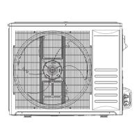
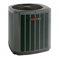
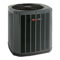
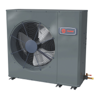
1.6 Product appearance .......................................................................... 9
2. Outlines and dimensions ............................................................ 10
3. Electrical data ............................................................................... 12
4. Capacities and selection data ..................................................... 13
4.1 Capacity characteristic charts ..........................................................13
4.2 Piping length correction factor....................................................... 20
5. Sound pressure data ................................................................... 21
6. Refrigerant cycle .......................................................................... 22
7. Wiring diagram ............................................................................. 24
7.1 Electrical wiring diagram ................................................................ 24
7.2 Control board picture ...................................................................... 26
7.2 Control board picture ...................................................................... 31
8. Filed setting .................................................................................. 32
8.1 Outdoor unit DIP switch .................................................................. 32
8.2 Running parameter check ............................................................... 34
9. Piping work and refrigerant charg .............................................. 37
9.1 MAX. length allowed ...................................................................... 37
9.2 Oil trap ............................................................................................. 37
9.3 Air tight test ..................................................................................... 38
9.4 Additional refrigerant charge ......................................................... 38
10. Installation tools and installation flow chart ........................... 39
10.1 Necessary tools and instrument list for installation ................... 39
10.2 Installation flow chart .................................................................... 41
11. Control mode .............................................................................. 42
12. Sensor parameter ...................................................................... 43