18
18-EB31D1-1F-EN
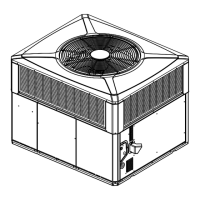
Table 5. Typical Rooftop Down Airflow Application with Frame
Return Air
Roof Flashing
Channel Iron Center Support
(center support required on all
frame applications).
Angle Iron Frame
Roof
Flashing
Supply
Air
DDuuccttwwoorrkk IInnssttaallllaattiioonn
AAttttaacchhiinngg DDoowwnnffllooww DDuuccttwwoorrkk ttoo RRooooff CCuurrbb
Supply and return air flanges are provided on the roof
curb for easy duct installation. All ductwork must be
run and attached to the curb before the unit is set into
place.
AAttttaacchhiinngg DDoowwnnffllooww DDuuccttwwoorrkk ttoo RRooooff FFrraammee
Follow these guidelines for ductwork construction:
Connections to the unit should be made with three (3)
inch canvas connectors to minimize noise and vibration
transmission.
Elbows with turning vanes or splitters are
recommended to minimize air noise and resistance.
The first elbow in the ductwork leaving the unit should
be no closer than two (2) feet from the unit, to minimize
noise and resistance.
To prevent leaking, do not attach the ductwork to the
bottom of the unit base. Refer to the bottom example in
Figure 9, p. 18
Figure 9. Attaching Down Airflow Ductwork
FIELD DUCT
UNIT DUCT
FLANGE
UNIT BASE
AIR PROOF
THIS SEAM
FIELD DUCT
UNIT DUCT
FLANGE
UNIT BASE
AIR PROOF
THIS SEAM
FIELD
DUCT
UNIT DUCT FLANGE
UNIT BASE
AIR PROOF
THIS SEAM
FIELD DUCT
UNIT DUCT
FLANGE
UNIT BASE
NOT RECOMMENDED
WATERPROOF SEAM
WITH BUTYL OR
SILICONE
SStteepp 44 —— UUnniitt IInnssttaallllaattiioonn