42
WSHP-SVX014J-EN
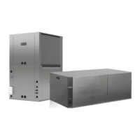
Figure 39. Step 1
2. Mount the waterside economizer to the unit. It is
secured to the unit using the five engagement holes
that were used for the filter brackets: three on top and
two on the bottom.
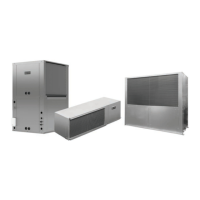
Figure 40. Step 2
3. Attach the filter brackets to the waterside economizer
using five screws. Install the air filter.
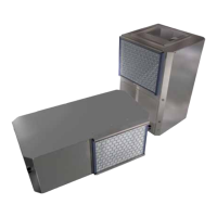
Figure 41. Step 3
4. Install the braided hose connecting point A (leaving the
WSE) to point B (entering the WSHP). Connect the
supply water to point D and the return water to point C.
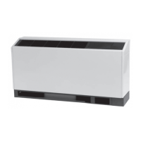
Figure 42. Step 4
5. Locate the entering water sensor that is located behind
the unit’s control box, and wire tie it to the water
SUPPLY side of the piping. The sensor must be
mounted before the two-position valve. Attaching the
sensor anywhere else will cause the WSE to not
operate correctly. Bundle up any excess sensor wire
and wire tie the bundle neatly.
6. Locate the WSE valve wires (35B (COM), 36B (OPEN),
37B (CLOSE)) behind control box, and connect to the
valve actuator. Bundle up any excess wire and wire tie
the bundle neatly. Direction of rotation is reversible with
switch.
7. Insulate the economizing piping package and the
associated hoses via field pipe insulation. Insulating the
Installation
 Loading...
