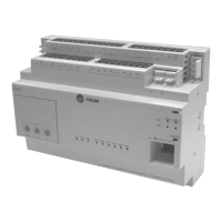
ACC-SVP01B-EN • BCI-I Integration Guide 29
Object Data Points and Diagnostic Data Points
Multi-State Input, 15
Economizer Decision
Method
Unit method to determine when the
economizer system is enabled.
1= Absolute Temperature
2= Relative Temperature
3= Absolute Enthalpy
4= Comparative Enthalpy
Multi-State Input, 17 Cooling Reset Type Status Indicates the type of cooling reset.
1= None
2= Outdoor Air
3= Zone
Multi-State Input, 18 Heating Reset Type Status Indicates the type of heating reset.
1= None
2= Outdoor Air
3= Zone
Multi-State Input, 19 Application Mode Status
Indicates the current application mode of
the equipment.
1 = Auto
2 = Heat
3 = Morning Warm-up
4 = Cool
5 = Night Purge
6 = Pre Cool
7 = Off
8 = Test
9 = Emergency Heat
10 = Fan Only
11 = Free Cool
12 = Ice-Making
13 = Max Heat
14 = Economy Mode
15 = Dehumidifying
16 = Calibrate
Multi-State Input, 20 Occupancy Mode Status
Indicates the current occupancy mode of
the unit.
1 = Occupied
2 = Unoccupied
3 = Occupied Bypass
4 = Occupied Standby
Multi-State Input, 21 Unit Stop Source
Source of the stop command that turned off
the equipment.
1= None
2= Emergency Stop
3= External Auto/Stop
4= Local HI
5= Remote HI
Multi-State Input, 22 Cooling Setpoint Source
Indicates the source of the space cooling
setpoint.
1= RTM Zone Sensor
2= Night Setback Panel
3= Human Interface
4= GBAS 0-5V
5= BAS/Network
6= GBAS 0-10V
Multi-State Input, 23 Heating Setpoint Source
Indicates the source of the space heating
setpoint.
1= RTM Zone Sensor
2= Night Setback Panel
3= Human Interface
4= GBAS 0-5V
5= BAS/Network
6= GBAS 0-10V
Multi-State Input, 24 Timed Override Status
Timed override request or cancel from zone
sensor.
1 = Idle
2 = On
3 = Cancel
Multi-State Input, 25 Cool Output 1
Indicates the commanded state of cooling
output 1.
1 = Off
2 = On
3 = Not Present
Multi-State Input, 26 Cool Output 2
Indicates the commanded state of cooling
output 2.
1 = Off
2 = On
3 = Not Present
Multi-State Input, 27 Cool Output 3
Indicates the commanded state of cooling
output 3.
1 = Off
2 = On
3 = Not Present
Multi-State Input, 28 Cool Output 4
Indicates the commanded state of cooling
output 4.
1 = Off|
2 = On
3 = Not Present
Multi-State Input, 29 Heat Output 1
Indicates the commanded state of heating
output 1.
1 = Off
2 = On
3 = Not Present
Multi-State Input, 30 Heat Output 2
Indicates the commanded state of heating
output 2.
1 = Off
2 = On
3 = Not Present
Multi-State Input, 31 Heat Output 3
Indicates the commanded state of heating
output 3.
1 = Off
2 = On
3 = Not Present
Table 7. Multistate Input (continued)
BCI-I Object
Identifier
Object Name Description Object States
 Loading...