BAS-SVX076C-EN
15
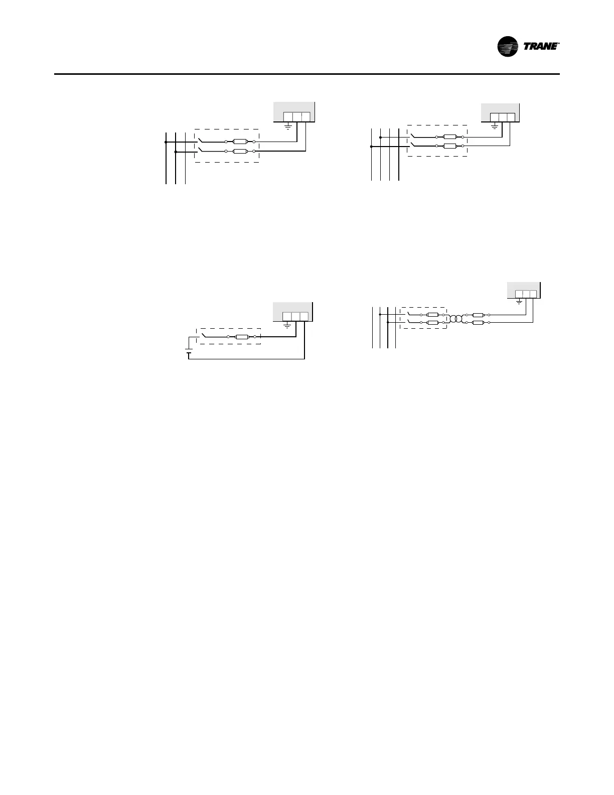
Figure 2. Control Power Diagrams
L1
1 2G
L2 L3
L1N L2 L3
1 2G
1 2G
L1N L2 L3
1 2G
#1: Direct Connect Control Power, Line-to-Line #2: Line-to-Neutral from 90 Vac to
347 Vac (UL) or 300 Vac (CE)
#3: DC Control power from 125 VDC
to 300 VDC (UL and CE max)
Line-to-Line from 90 Vac to 600 Vac (UL). In UL
installations the lines may be floating (such as
a delta). If any lines are tied to an earth (such as
a corner grounded delta), refer to the
Line-to-Neutral installation limits. In CE
compliant installations, the lines must be
neutral (earth) referenced at less than 300 Vac
L-N
#4: Control power transformer may be wired
L-N or L-L. Output to meet meter
input requirements
Fuse Recommendations
Keep the fuses close to the power source. For selecting fuses and circuit breakers, use the
following criteria:.
• Select current interrupt capacity based on the installation category and fault current
capability
• Select over-current protection with a time delay.
• Use a voltage rating sufficient for the input voltage applied.
• Provide over-current protection and disconnecting means to protect the wiring.
NNoottee:: . For AC installations, use Trane AH04 or equivalent. For DC installations, provide
external circuit protection. Suggested: 0.5A, time delay fuses rated for DC operation at
or above the supply voltage
• Use the earth connection (G) for electromagnetic compatibility (EMC), not a protective earth
ground.
WWiirriinngg