5
Section 3. Unit Preparation
3.1 Prepare The Unit For Installation
STEP 1 - Check for damage and report promptly to
the carrier any damage found to the unit.
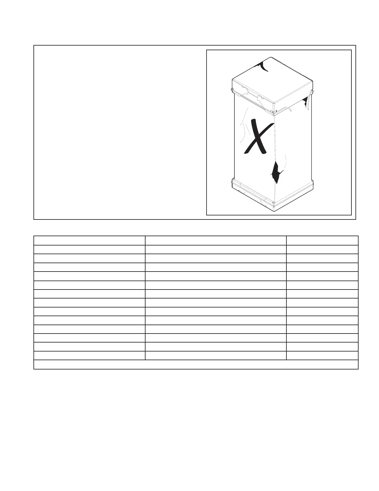
Note: If the unit must be transported in a horizontal
position, it must be laid on its back (marked “REAR”
on carton).
Note: Remove the cardboard from the bottom of the
blower. Cut the tie wrap and remove the foam block
located at the motor.
Note: After the unit is removed from the carton,
release pressure from the coil to verify coil is
pressurized and leak free.
3.2 Unit Accessories
Accessory Number Description
Fits Cabinet Size 1
BAYECAA05LG1 Electric Heater, 5kW, Lugs, 24V Control, 1 Ph A1
BAYECAA08LG1 Electric Heater, 8kW, Lugs, 24V Control, 1 Ph A1
BAYECAA10LG1 Electric Heater, 10kW, Lugs, 24V Control, 1 Ph A1
BAYSFSCABAA
Supply Duct Flange A1 1
A1
BAYRETFLGAA Return Duct Flange A A1
TASB175SB Plenum Stand with Sound Baffle A A1
BAYFRKIT100 Front Return Kit A1
BAYBRFBX100 Bottom Return Filter Box A1
BAYWMKIT001 Wall Mount Kit A1
BAYLVKIT100A Low Voltage Conduit Entry Kit A1
BAYECPDKIT1A Pull Disconnect Kit A1
BAYAHTXV1836 R-22 TXV Conversion Kit A1
BAYCNDPIP01A 3/4” PVC Threaded Pipe Kit foam seal (10 per box) A1
1 GAF2A0A18-36 Cabinet is one piece 17.5” wide
Table 3.1