23
Section 10. Refrigerant Line
10.1 Refrigerant Line Connection Sizes
10.2 Refrigerant System Layout
Refrigerant Line Set and Connection Sizes
Model
Vapor Line
Connection
Liquid Line
Connection
GAF2A0A36S3AEC, GAF2A0A36S3ASC
3/4 3/8
GAM2A0C48S4ASC
7/8 3/8
GAM2A0C60S5ASC
7/8 3/8
Notes:
1. This table indicates the tubing connection diameters at the indoor coil. A field supplied reducing coupling may be required.
2. All listed systems are tested with 25 feet of refrigeration tubing; the rated tubing diameters are located in the electronic
performance data system.
3. If the refrigeration lines exceed 60 feet in linear length and / or if alternate size refrigeration tubing is present at the job,
please consult SS-APG006-EN or 32-3312-**(latest version)
Table 10.1
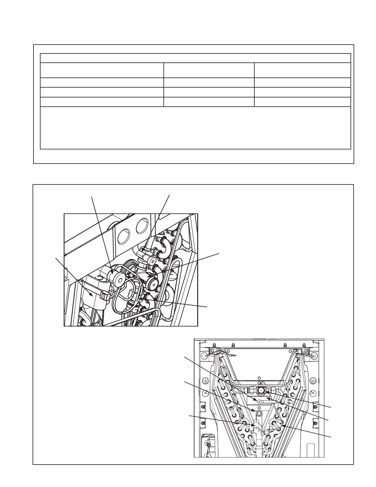
TXV
Vapor Line
Liquid Line
External
Equalizer
Line
TXV
Sensing
Bulb
Note: An inlet strainer is located inside
the liquid line mechanical fitting.
GAM2
TXV
Braze
Shield
Vapor Line
Liquid Line
External
Equalizer
Line
TXV
Sensing
Bulb -
(No
insulation
required)
GAF2