33
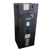
Section 15. Filters
15.1 Filter Considerations
Filter in GAM2
air handler
cabinet
(Upflow
Application)
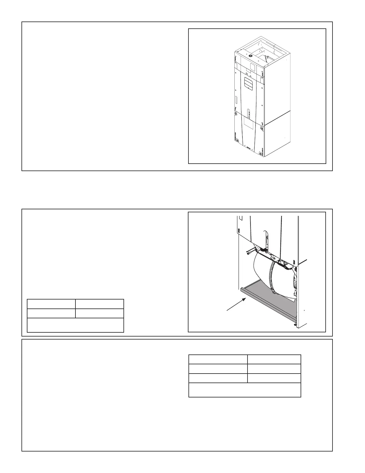
GAM2 air handlers
• A filter must be installed within the system.
• A filter channel is provided in the unit, at the bot-
tom of the Blower/Filter compartment.
• For customer ease of fil ter maintenance, it is
recommended that a properly sized remote filter
grill(s) be installed for units that are difficult to
access. Airflow should not exceed the maximum
rated velocity of the filter being used.
Cabinet Size* C
Filter Size 22 x 20
* Cabinet size is indicated by the 7th digit in
model number.
Table 15.1 GAM2 Filter Sizes
STEP 6 - Reinstall all panels before starting the air
handler.
NOTE: After replacing all panels, loosen the Line
Set Panel screws approximately 1/4 - 1/2 turn. This
will improve the seal between the Heater Panel and
Line Set Panel.
GAF2 air handlers
• Since a filter option is not included within the air
handler, a remote filter must be installed with the
system.
• For customer ease of fil ter maintenance, it is
recommended that a properly sized remote filter
grill(s) be installed for units that are difficult to
access. Airflow should not exceed the maximum
rated velocity of the filter being used.
• A bottom return filter kit BAYBRFBX100 or a front
return filter kit BAYFRKIT100 may be installed.
Accessory Kit* Filter Size
BAYBRFBX100 16” x 20”
BAYFRKIT100 16” X 16”
*Kits are for GAF2 one piece A Cabinets. Cabinet
size is indicated by the 7th digit in model number.
Table 15.2 GAF2 Filter Sizes