2
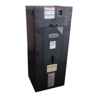
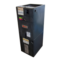
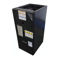
Note: Representative illustrations only included in this document. Most illustrations display the upflow configuration.
Table of Contents
Section 1. Safety Information.............................................................................................................3
Section 2. Unit Design.......................................................................................................................4
Section 3. Unit Preparation................................................................................................................6
Section 4. Optional Cabinet Disassembly..........................................................................................7
Section 5. Place Unit at Location......................................................................................................11
Section 6. Unit Location Considerations..........................................................................................12
Section 7. Setting the Unit - Vertical Installation..............................................................................17
Section 8. Setting the Unit - Horizontal Installation..........................................................................19
Section 9. Connecting the Duct work...............................................................................................20
Section 10. Refrigerant Line............................................................................................................21
Section 11. Refrigerant Line Brazing...............................................................................................22
Section 12. Condensate Drain Piping..............................................................................................25
Section 13. Electrical - High Voltage................................................................................................27
Section 14. Electrical - Low Voltage ................................................................................................30
Section 15. Product Specifications .................................................................................................33
Section 16. Airflow Performance .....................................................................................................34
Section 17. Wiring Data ..................................................................................................................40
Section 18. Distance From Belly Band To Shaft Face Of Motor For Minimum Vibration .................43
Section 19. Wiring Diagram ............................................................................................................44
Section 20. Unit Outline Drawing.....................................................................................................45
Section 21. Filters............................................................................................................................46
Section 22. Start Up.........................................................................................................................46
Section 23. 2-Stage Outdoor Adjustment........................................................................................48
Section 24. Sequence of Operation.................................................................................................50
Section 25. Checkout Procedures....................................................................................................51
Section 26. Troubleshooting ............................................................................................................52
ALL phases of this installation must comply with NATIONAL, STATE AND LOCAL CODES
Important: This Document is customer property and is to remain with this unit. Please return to service information
pack upon completion of work.
Important: These instructions do not cover all variations in systems nor provide for every possible contingency to be met
in connection with the installation. Should further information be desired or should particular problems arise which are not
covered sufficiently for the purchaser’s purposes, the matter should be referred to your installing dealer or local distributor.
Note: The manufacturer recommends installing ONLY A.H.R.I. approved, matched indoor and outdoor systems. Some
of the benefits of installing approved matched indoor and outdoor split systems are maximum efficiency, optimum per-
formance, and the best overall system reliability.
Note: Condensation may occur on the surface of the air handler when installed in an unconditioned space. When units are in-
stalled in unconditioned spaces, verify that all electrical and refrigerant line penetrations on the air handler are sealed completely.
Important: The GAM5 air handlers will only use the following internal electric heaters:
Important: GAM5B0C60M51EB air handler applied in downflow or horizontal configurations should not exceed 2000 CFM.
Airflow above 2000 CFM could result in water blow-off. For verification, see airflow table.
BAYEAAC04BK1
BAYEAAC04LG1
BAYEAAC05BK1
BAYEAAC05LG1
BAYEAAC08BK1
BAYEAAC08LG1
BAYEAAC10BK1
BAYEAAC10LG1
BAYEAAC10LG3
BAYEABC15BK1
BAYEABC15LG3
BAYEABC20BK1
BAYEACC25BK1
 Loading...


