24
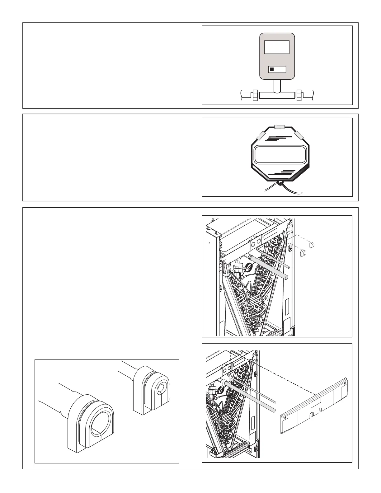
STEP 10 - Replace the Line Set panel.
1. Allow time for tubing to cool.
2. Install grommets to line set piping.
Note: A slight amount of dish soap can be used to
aid in the installation of the grommets. Remove any
excess from the tubing and grommet after the grommet
is installed.
3. Slide the bottom of the Line Set panel down over
the refrigerant lines and grommets. The grommets
will seal the line openings.
Note: If installing in a horizontal application, complete
the condensate connection preparations per Section
12, Step 3 before installing the Line Set panel.
4. Tighten screws on the Line Set panel.
Important: Do not open the service valves until the
refrigerant lines and indoor coil leak check and evacu-
ation are complete.
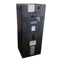
STEP 8 - Evacuate until the micron gauge reads no
higher than 350 microns, then close off the valve to the
vacuum pump.
STEP 9 - Observe the micron gauge. Evacuation is
complete if the micron gauge does not rise above 500
microns in one (1) minute.
Once evacuation is complete blank off the vacuum
pump and micron gauge, and close the valves on the
manifold gauge set.
Note: Charge system using Outdoor unit’s Installer
Guide or Service Facts.
0350
Microns
ON
OFF
See enlarged
illustration for
orientation