29
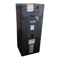
STEP 6 - Reinstall all panels before starting the air
handler.
NOTE: After replacing all panels, loosen the Line
Set Panel screws approximately 1/4 - 1/2 turn.
This will improve the seal between the Heater
Panel and Line Set Panel.
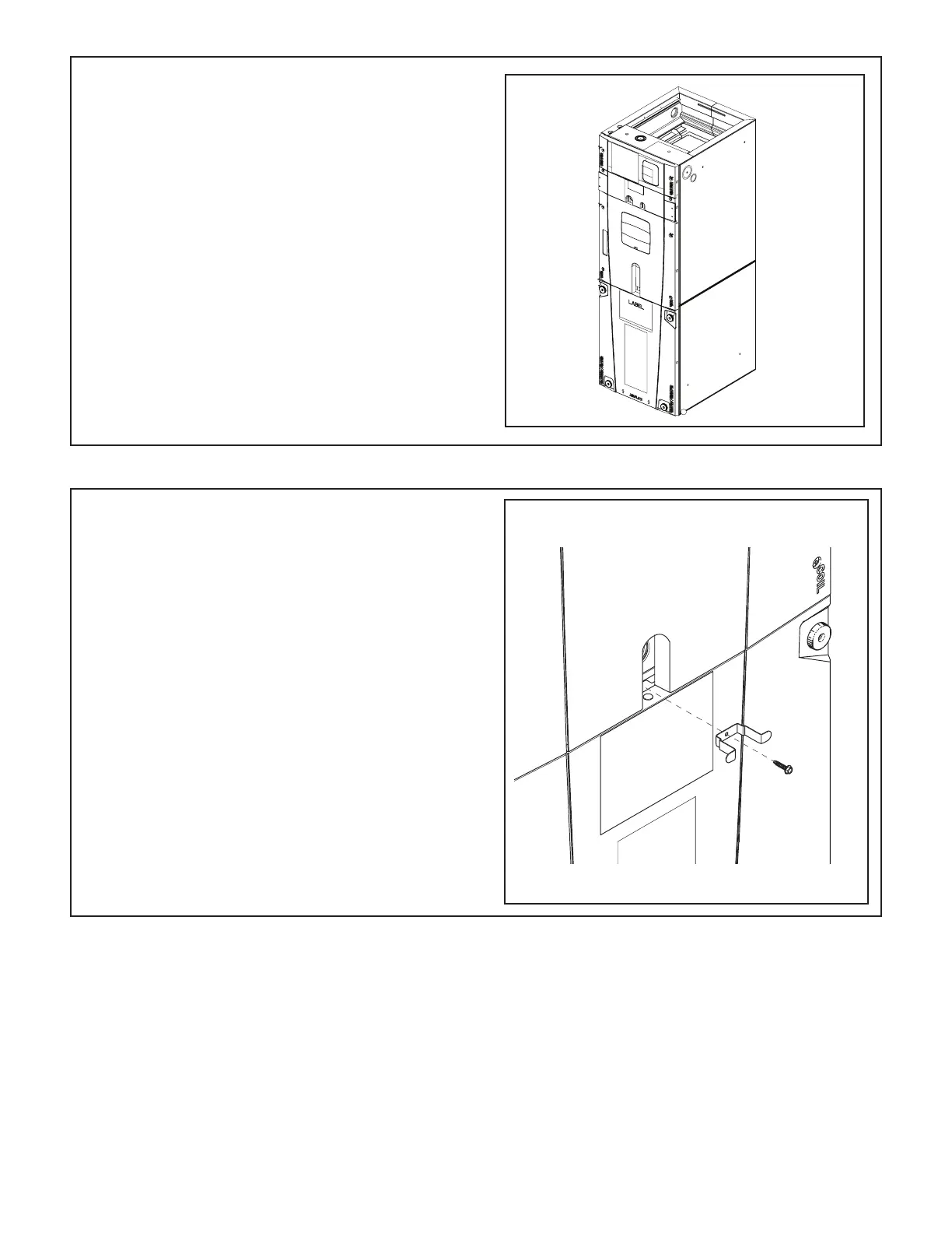
13.3 Secure Coil (All Applications)
STEP 1 - Remove screw and coil panel bracket from
documentation packet.
STEP 2 - Place the coil panel bracket into position and
use screw to secure the coil panel bracket and seal
plate to the support bar.
Important: The Coil Seal Plate and screw secure the
coil in the center of the air handler. Failure to follow
these steps can prevent the Coil Panel from being
easily replaced on the unit.
Important: The Blower Panel may be removed if
needed to help align the new screw with the seal plate
and crossmember.
Important: For the 5 ton air handler model, tap 5
should not be used in the downflow or horizontal
orientations. Using Tap 5 could result in water
blowing off the coil.