38
Note: Heating and cooling speeds are the same, factory
set at Speed Tap #4.
Note: A “G” only signal from the comfort control will run
the blower at a lower speed, factory set at Speed Tap #1.
See the Sequence of Operation for additional information.
Note: Speed Tap 1 is NOT used for two stage systems.
Two stage systems will require an airflow adjustment.
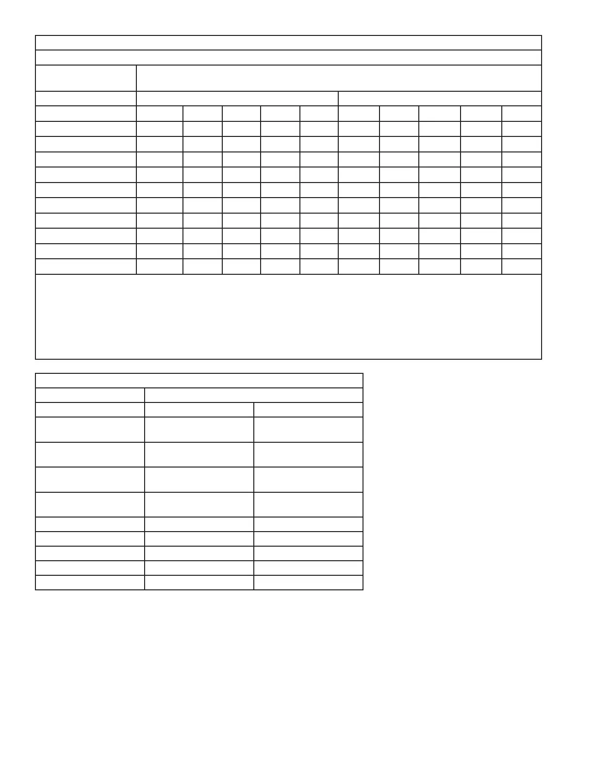
AIRFLOW PERFORMANCE
GAM5B0C48M41EB
EXTERNAL STATIC
(in w.g)
AIRFLOW (CFM)
Speed Taps - 230 VOLTS Speed Taps - 208 VOLTS
5 4 † 3 2 1 5 4 † 3 2 1
0 1913 1770 1694 1593 866 1910 1767 1691 1590 863
0.1 1874 1730 1653 1547 791 1868 1724 1647 1541 785
0.2 1834 1690 1611 1505 699 1825 1681 1602 1496 690
0.3 1791 1646 1567 1456 620 1780 1635 1556 1445 609
0.4 1748 1600 1521 1410 537 1734 1586 1506 1396 522
0.5 1708 1556 1476 1367 453 1691 1539 1459 1350 437
0.6 1668 1516 1436 1326 370 1648 1496 1416 1306 351
0.7 1629 1475 1394 1283 - 1607 1452 1372 1260 -
0.8 1588 1435 1352 1236 - 1563 1410 1327 1211 -
0.9 1541 1390 1304 1183 - 1513 1362 1276 1156 -
NOTES:
1. Values are with wet coil and without filters.
2. Contact your particular filter manufacturer for pressure drop data.
3. Electric heater pressure drop is negligible and is included within the airflow data.
4. Tap 1 is an continuous fan speed tap for single stage systems. Airflow adjustment is required for 2 stage systems.
See Airflow adjustment section.
5. † Factory Setting
GAM5B0C48M41SB, GAM5B0C48M41EA MINIMUM HEATER AIRFLOW CFM
Heater Minimum Air Speed Tap
Without HP With HP
BAYEAAC04BK1
BAYEAAC04LG1
Tap 2 Tap 3
BAYEAAC05BK1
BAYEAAC05LG1
Tap 2 Tap 3
BAYEAAC08BK1
BAYEAAC08LG1
Tap 2 Tap 3
BAYEAAC10BK1
BAYEAAC10LG1
Tap 2 Tap 3
BAYEAAC10LG3 Tap 2 Tap 3
BAYEABC15BK1 Tap 3 Tap 4
BAYEABC15LG3 Tap 3 Tap 4
BAYEABC20BK1 Tap 3 Tap 4
BAYEACC25BK1 Tap 4 Tap 5