RT-SVX063G-EN
53
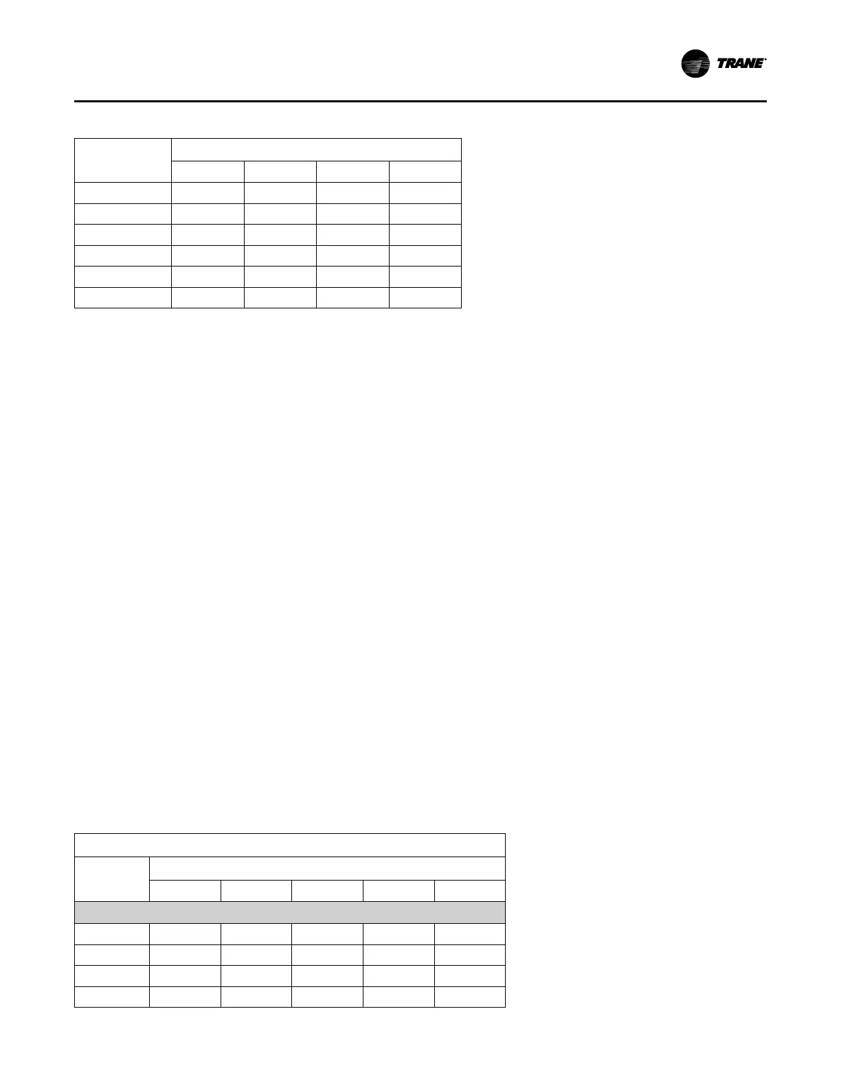
Table 20. Return air pressure increase (continued)
CFM
Return Air Damper Position
#1 #2 #3 #4
14000 0.00 0.11 0.25 0.43
16000 0.00 0.13 0.28 0.55
18000 0.00 0.14 0.31 0.67
20000 0.00 0.15 0.33 0.81
22000 0.00 0.16 0.35 0.96
24000 0.00 0.17 0.37 1.13
Units with Dual Actuators (60, 70 and 75 Ton)
The installer can adjust the stroke of the direct drive
actuator on the O/A & R/A dampers to compensate for
various R/A duct losses. Table 21, p. 53 and Table 22, p.
54 list the pressure drops for various actuator limit positions
based on the air flow (CFM) and configuration. The
actuator stroke limit can be adjusted between 33% and
100% of full stroke. To adjust the O/A or R/A damper for the
correct pressure drop:
1. Drill a 1/4" hole through the unit casing up stream of the
return air dampers. Use a location that will produce an
accurate reading with the least amount of turbulence –
several locations may be necessary, then average the
reading.
2. Measure the return duct static pressure.
3. Compare the static pressure reading to the static
pressure ranges and linkage positions in Table 21, p.
53 or Table 22, p. 54 for the unit configuration, unit size
and operating CFM.
If the static pressure reading is greater than the
pressure listed in Table 21, p. 53 or Table 22, p. 54 for
outside air damper position 100% then adjust the
outside air damper actuator to balance the outside air
damper pressure drop against the return static
pressure, using the following steps.
If the static pressure reading is less than the pressure
listed in Table 21, p. 53 or Table 22, p. 54 for outside
air damper position 100%, then determine the
appropriate return air pressure drop increase needed.
Identify the correct return damper actuator position
using Table 23, p. 54. Then, adjust the return air
damper actuator to balance the outside air damper
pressure drop against the return static pressure using
the following steps.
If no adjustment is necessary, proceed to step 6.
4. To set the actuator stroke limit:
a. Loosen the screw that secures the angle of rotation
limiter on the actuator adjacent to the damper drive
shaft clamp.
b. Move the limiter to the desired % open position and,
making sure the limiter teeth are engaged, retighten
the screw.
5. After setting the end stop, the actuator needs to be
cycled through its auto-adapt feature to re-scale the
control range. With 24 VAC power applied to the
actuator, turn the control signal reversing switch
forward and back again two times. Within a few
seconds, the actuator will cycle itself to the new limiter
position and then back to zero.
Note: This process may take up to 5 minutes.
The actuator will then be set to respond to the 2-10
VDC control signal to cycle within the new range of
rotation set by the limiter. Verify that the control signal
reversing switch is set back to its original default
position - Y = 0, set to CCW, which is the same
direction as spring return.
6. Plug the holes (made during Step 1) after the proper
adjustments have been made.
Table 21. Outside Air Pressure Drop (inches w.c.) – No Traq™
No Traq™
CFM
Outside Air Damper Position
100% 75% 55% 45% 33%
60, 70 and 75 Ton
14000 0.16 0.30 0.43 0.60 1.10
16000 0.20 0.39 0.57 0.80 1.52
18000 0.25 0.49 0.73 1.03 2.00
20000 0.29 0.60 0.91 1.29 2.56
Installation
 Loading...


