EasyManua.ls Logo

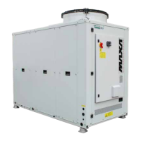
Trane MAXA i-HPV5H 0140 User Manual

Trane MAXA i-HPV5H 0140
48 pages
To Next Page IconTo Next Page
Page #1 background imageLoading...
Page #1 background image
www.maxa.it
i-HPV5H 0140
i-HPV5H 0250
i-HPV5H 0260
i-HPV5H 0270
R32
Chiller and Inverter Air/Water heat pumps with axial fan
User-Installer Manual
Models
This manual has been created for informave purpose. The company declines any responsibility for the results of any projecng or any installaon based on the
explanaons and/or on the technical specicaons provided in this manual. It is besides forbidden the reproducon under any form of the texts and of the gures
contained in this manual. This manual is a translaon from the ocial italian language version. For reasons of environmental respect the Company will not provide
the hard copy in the original language which could be directly requested or downloaded from the Company website at any me. In case of any dispute, the original
language manual will be the trusted one. Even paral reproducon PROHIBITED © Copyright - Advanx SpA

Table of Contents

Questions and Answers:

Trane MAXA i-HPV5H 0140 Specifications

General IconGeneral
BrandTrane
ModelMAXA i-HPV5H 0140
CategoryHeat Pump
LanguageEnglish

Summary

PURPOSE AND CONTENTS OF THE MANUAL

HOW TO KEEP THE MANUAL

Instructions for storing and maintaining the manual for accessibility and longevity.

GRAPHIC SYMBOLS USED IN THE MANUAL

Explanation of hazard, prohibition, and important safety symbols within the manual.

NORMATIVE REFERENCES

PERMITTED USE

GENERAL SAFETY GUIDELINES

WORKERS' HEALTH AND SAFETY

Outlines directives and employer obligations for worker safety, referencing EU regulations.

PERSONAL PROTECTIVE EQUIPMENT

SAFETY SIGNS

REFRIGERANT SAFETY DATA SHEET

SPECIFIC R32 GAS WARNINGS

R32 GAS CHARGE

R32 GAS DISPOSAL

SAFETY RULES FOR R32 GAS TRANSPORT AND STORAGE

INSTALLATION

GENERAL

General instructions for unit installation, emphasizing adherence to manual guidelines and precautions.

TRANSPORT AND STORAGE LIMIT TEMPERATURE

LIFTING AND HANDLING

POSITIONING AND MINIMUM TECHNICAL CLEARANCES

DIMENSIONS

Standard version

Presents dimensional data and connection details for the standard version of the unit.

Version with tank kit

Shows dimensional data and connection specifics for the unit version equipped with a tank kit.

CENTRE OF GRAVITY AND DAMPERS LOCATION

ACCESSING THE INNER PARTS

Access to the inside of the unit on the electrical panel side

Instructions on how to access the unit's interior via the electrical panel door for maintenance.

PLUMBING CONNECTIONS

Features of the circuit water

Specifies the maximum allowed chemical-physical properties for the circuit water to ensure optimal unit operation.

Hydraulic diagram inside the unit

Provides a legend and diagrams for hydraulic connections for various unit configurations.

Drainage system

Filling / Discharge of the plant

ELECTRICAL CONNECTIONS

Access to electric panel

Information on accessing the unit's electrical panel and the procedure for opening the door.

Power supply

Guidance on electrical wiring, grounding, cable sections, and tightening torques for power supply connections.

User terminal block

Details the connections available on the user terminal block for various functions and inputs/outputs.

Control logics

Fuses

FUNCTIONAL DIAGRAMS

i-HPV5H

Presents conceptual diagrams and a legend for the i-HPV5H model's functional layout.

START UP

SWITCHING ON THE UNIT

Step-by-step instructions for powering on the unit, including initial checks and standby duration.

INSTRUCTIONS FOR THE USER

SHUTDOWNS FOR LONG PERIODS

MAINTENANCE AND PERIODIC CHECKS

GENERALITY

General guidelines for unit maintenance, including cleaning coils and general checks.

CLEANING OF EXTERNAL SURFACES

EXTRAORDINARY MAINTENANCE

DECOMMISSIONING

RESIDUAL RISK

TECHNICAL DATA

TECHNICAL SHEET HEAT PUMP

Presents performance data for the heat pump according to standard 14511:2018, covering various operating conditions.

UNIT AND AUXILIARY ELECTRICAL DATA

OPERATING LIMITS

EVAPORATOR WATER FLOW RATE

Details minimum and maximum water flow rates for the evaporator, emphasizing safety implications of insufficient flow.

COLD WATER PRODUCTION (SUMMER MODE)

Specifies operating temperature limits for cold water production, including glycol usage for low temperatures.

HOT WATER PRODUCTION (WINTER MODE)

Outlines temperature limits for hot water production, warning against values outside the specified range.

AMBIENT AIR TEMPERATURE AND SUMMERISED TABLE

Provides operating temperature ranges for summer and heat pump modes, including tables for different conditions.

USER INTERFACE - CONTROLLER

MENU

Explains the main menu structure for navigating unit functions and settings.

SETPOINT MENU

Details how to view and edit various setpoints for summer, winter, and DHW modes.

ALARM MENU [ERR]

Describes how to access and view active alarms and errors displayed on the unit.

TROUBLESHOOTING

Related product manuals