SSP-SVX001B-EN
25
Unit Power Supply
The installer must provide line voltage circuit(s) to the
unit main power terminals as shown by the unit wiring
diagrams. Adhesive backed diagrams are affixed inside
the control box cover panel. Wiring diagrams are also
available through e-Library or by contacting a local
sales office. Power supply must include a disconnect
switch in a location convenient to the unit. Ground the
unit according to local codes and provide flexible
conduit if codes require and/or if vibration transmission
may cause noise problems.
IImmppoorrttaanntt:: All wiring must comply with applicable
local and national (NEC) codes. Type and
location of disconnect switches must
comply with all applicable codes.
WWAARRNNIINNGG
PPrrooppeerr FFiieelldd WWiirriinngg aanndd GGrroouunnddiinngg
RReeqquuiirreedd!!
FFaaiilluurree ttoo ffoollllooww ccooddee ccoouulldd rreessuulltt iinn ddeeaatthh oorr
sseerriioouuss iinnjjuurryy..
AAllll ffiieelldd wwiirriinngg MMUUSSTT bbee ppeerrffoorrmmeedd bbyy qquuaalliiffiieedd
ppeerrssoonnnneell.. IImmpprrooppeerrllyy iinnssttaalllleedd aanndd ggrroouunnddeedd
ffiieelldd wwiirriinngg ppoosseess FFIIRREE aanndd EELLEECCTTRROOCCUUTTIIOONN
hhaazzaarrddss.. TToo aavvooiidd tthheessee hhaazzaarrddss,, yyoouu MMUUSSTT ffoollllooww
rreeqquuiirreemmeennttss ffoorr ffiieelldd wwiirriinngg iinnssttaallllaattiioonn aanndd
ggrroouunnddiinngg aass ddeessccrriibbeedd iinn NNEECC aanndd yyoouurr llooccaall//
ssttaattee//nnaattiioonnaall eelleeccttrriiccaall ccooddeess..
NNOOTTIICCEE
UUssee CCooppppeerr CCoonndduuccttoorrss OOnnllyy!!
FFaaiilluurree ttoo uussee ccooppppeerr ccoonndduuccttoorrss ccoouulldd rreessuulltt iinn
eeqquuiippmmeenntt ddaammaaggee aass tthhee eeqquuiippmmeenntt wwaass nnoott
ddeessiiggnneedd oorr qquuaalliiffiieedd ttoo aacccceepptt ootthheerr ttyyppeess ooff
ccoonndduuccttoorrss..
Low Voltage Wiring
Mount the indoor thermostat, zone sensor, or
programmable zone sensor in accordance with the
corresponding thermostat installation instructions.
Install color-coded, weather-proof, multi-wire cable
according to the field wiring instructions (see “Field
Wiring,” p. 26).
NNoottee:: Refer to thermostat or zone sensor wire
installation guide for proper wire gauge.
Symbio™™ Controls
Wiring shown with dashed lines is to be furnished and
installed by the customer. All customer supplied wiring
must be copper only and must conform to NEC and
local electrical codes. Codes may require line of sight
between disconnect switch and unit.
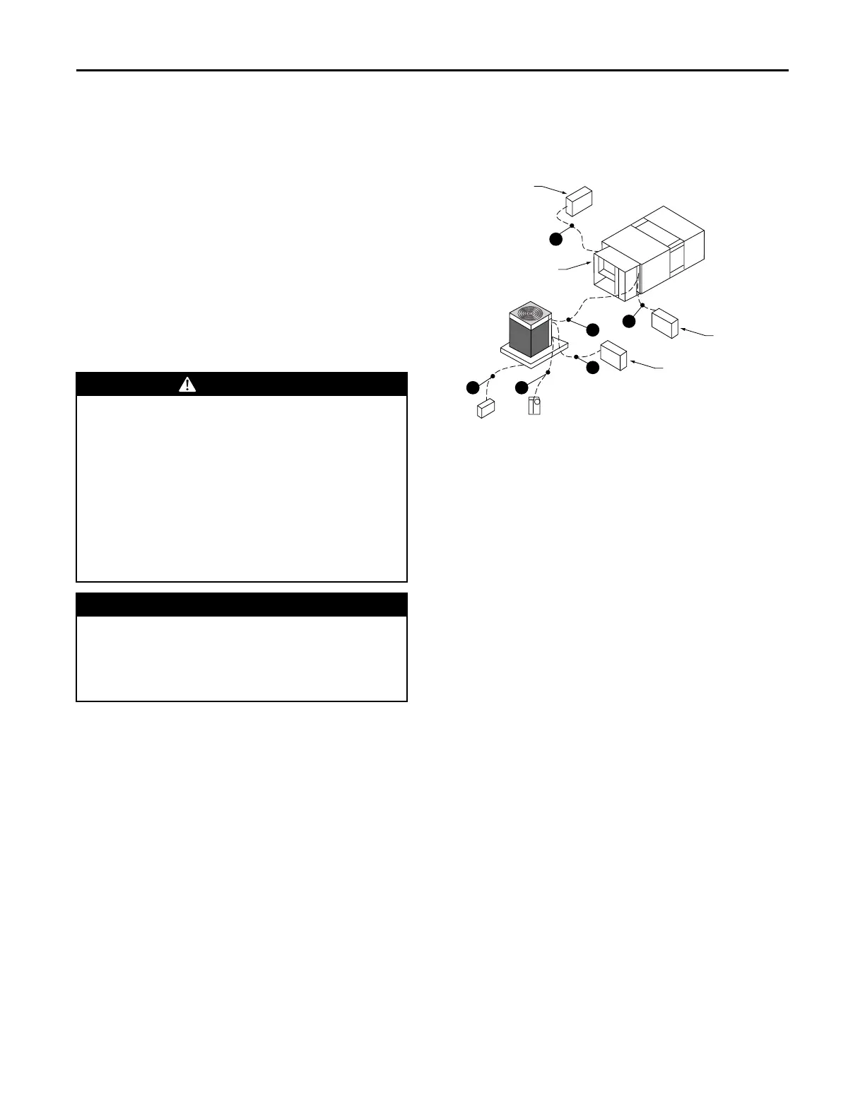
Figure 14. Symbio™™ jobsite connections
Zone Sensor
See Note 2
T’stat
See Note 2
Air Handler
Disconnect Switch
(By Others)
Disconnect Switch
(By Others)
See Note 1
Electric
Heat Accessory
Disconnect Switch
(By Others)
See Note 1
B
A
B
D
EC
PPoowweerr WWiirreess
A. 3 wires, line voltage for 3 phase, (2 wires for single
phase) 1 grounding wire
B. 3 wires, line voltage for 3 phase, (2 wires for single
phase) 1 grounding wire
CCoonnttrrooll WWiirreess
C. Heat Pump thermostat: 6 to 9 wires depending on
T’stat options and stages of cooling and heating
D. Wiring between indoor and outdoor unit: 5 to 11
wires depending on unit control options*
E. Zone Sensor: 4 to 7 wires depending on zone sensor
model*
*Communication signal wires require twisted pairs.
Refer to unit schematics for identification of twisted
pairs.
NNootteess::
1. When electric heater accessory is used,
single point power entry or dual point power
entry is field optional. Single point power
entry option is through electric heater only.
2. ***Choose only one of the following;
Thermostat, Mechanical Zone Sensor,
Programmable Zone Sensor Panel or BAS
Zone Sensor.
IImmppoorrttaanntt:: For the EDC switch to be functional and
thereby facilitate reliable unit operation,
make the EDC connections from the indoor
to the outdoor control boxes.
IInnssttaallllaattiioonn
 Loading...