Installation
36 SO-SVN048A-EN
Note: See “Dimensions,” p. 9 for conduit location
dimensions.
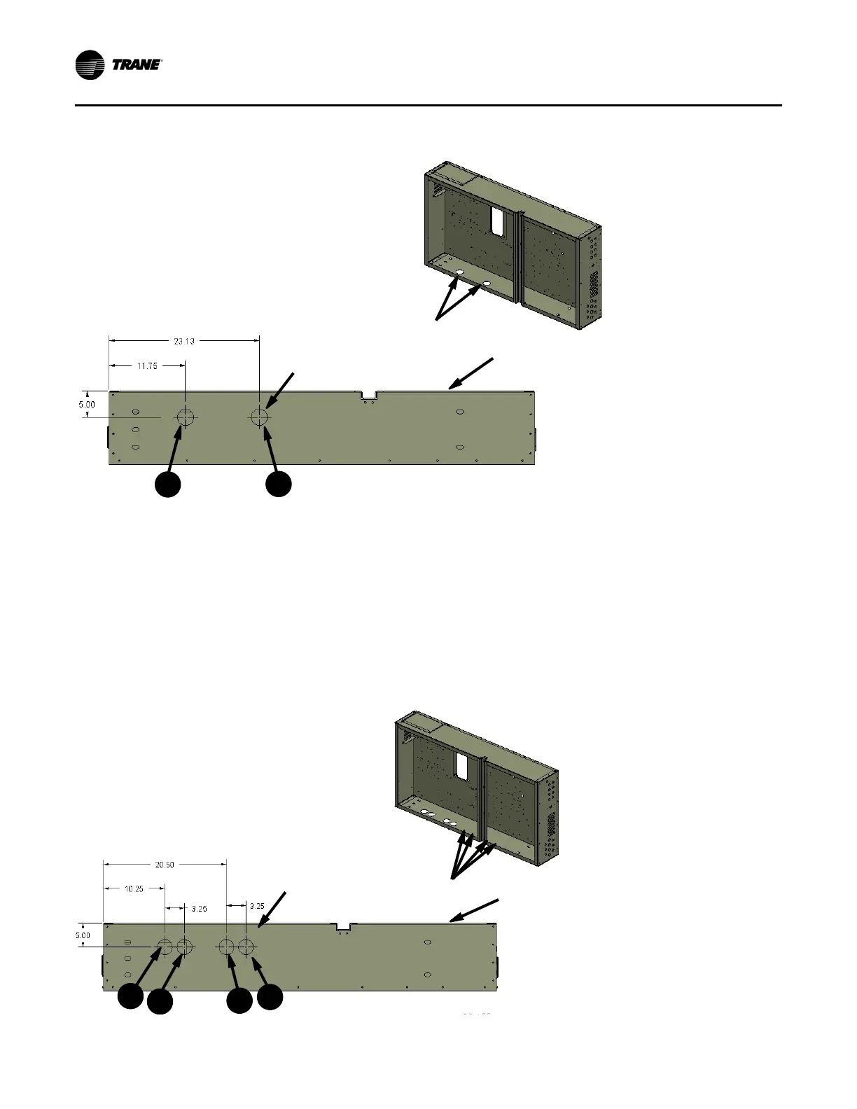
Panel Preparation – Close Mount
(Kit 2 – 4 conduit)
Refer to Figure 37 during the following procedure.
2. Drill four 2.5-inch diameter holes at Locations 1– 4, as
shown in Figure 37. These holes will be used to route the
power wire which connects the unit to the AFD.
Notes:
• Test-fit the 2.5-inch conduit fittings at the locations to
ensure the conduit and or fitting will not interfere with the
unit evaporator and or panel before drilling holes.
• Depending on the unit’s evaporator size the holes may be
located further inward than specified without interference
between conduit and evaporator. Locating the holes
further inward will aid in harness installation later. Before
drilling, make sure conduit and fittings will not interfere with
evaporator or panel door.
Figure 36. Conduit hole locations
2X Holes Drilled
Panel Front
Panel Bottom
2X Ø 2.5
2
1
Figure 37. Power conduit hole locations
2-4X Holes Drilled
Panel Front
Panel Bottom
2-4X Ø 2.5
3
1
4
2