Installation
SO-SVN048A-EN 39
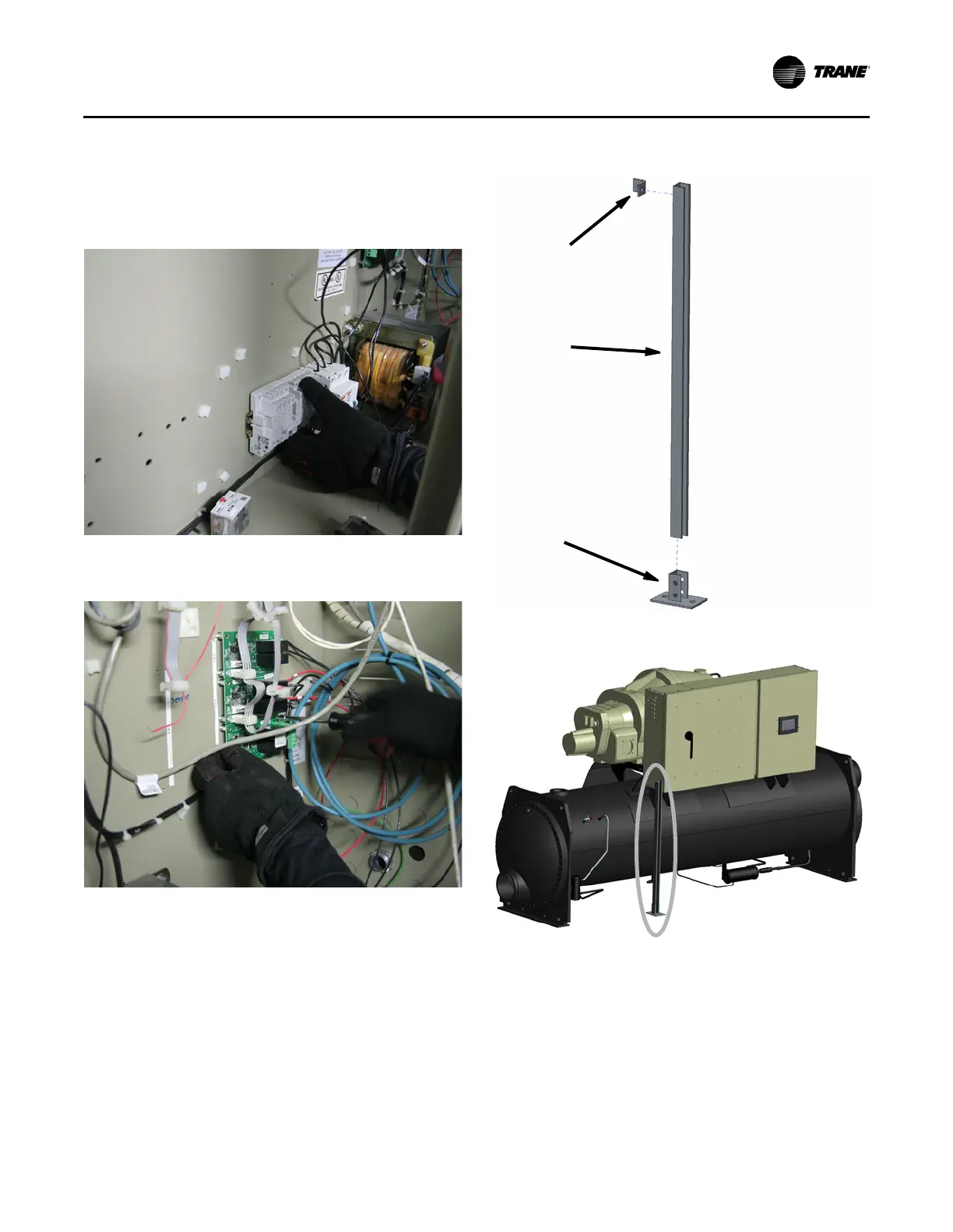
6. Install 1K1 and 1K2 relay sockets and relays (8/9) on
existing 7.5-inch din rail (10) where Fuse 1F1/2/3 was
removed.
7. Install din rail end-stops (4) on din-rail (10).
8. If not already installed, install dual relay output 1A8 (12).
9. Remove all metal chips and shavings from inside the
panel, and remove any loose debris, wires, or parts.
Conduit Support and Conduit
Installation (Kit 1 and Kit 2)
1. Assemble and install the supplied strut channel; refer to
Figure 45 and Figure 46.
Note: Make sure the position of the strut channel does
not interfere with panel door opening. Strut channel
may need to be cut to height (anchor bolts and
impact drill for concrete).
2. Route control wire and Modbus
®
cable along the bottom
side of panel and secure with provided loop-clamps; refer
to see Figure 47.
Note: Be sure to leave enough wire length to route wire
inside the control panel and the AFD and reach the
termination points.
3. Cut four 16 AWG wires to the appropriate lengths and
route through the 3/4-inch conduit.
Figure 43. 1K1, 1K2 relay socket
Figure 44. Dual relay 1A8 install
Figure 45. Strut channel assembly
Figure 46. Strut channel installed
L-Bracket
Strut Channel
Strut Channel
Base