Installation
SO-SVN048A-EN 45
4. Replace the front panel of the pedestal base.
Panel Power Wiring
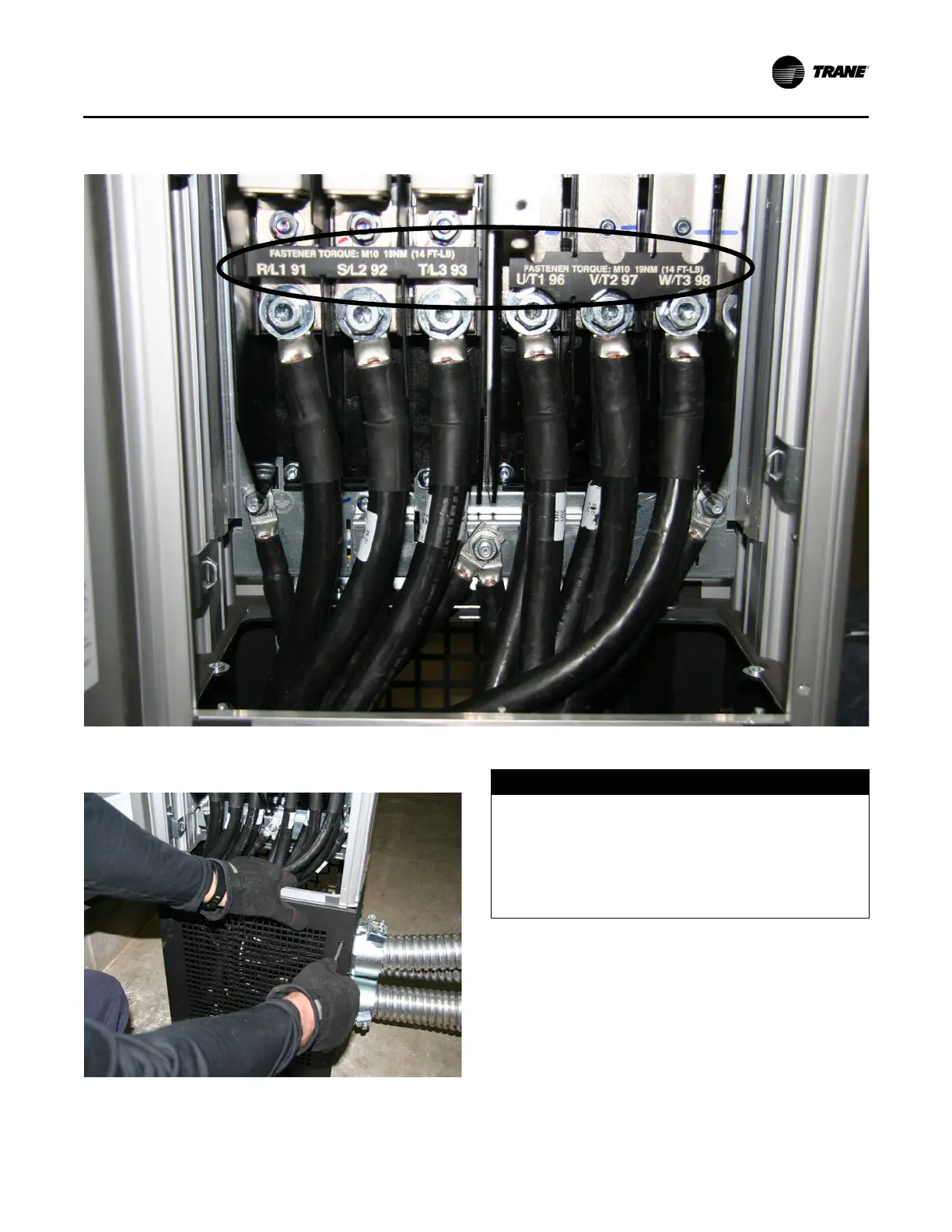
5. After verifying proper phasing between the drive and motor
terminals with an Ohmmeter, install power wire at the
breaker/terminal according to the provided schematics.
Refer to Figure 42, p. 38 to confirm phase designations.
6. Output wire from the drive to the motor terminals needs to
be routed through the center of the provided cores. Install
power wire at the motor terminals according to the
provided schematics.
Figure 61.
Figure 62.
NOTICE
Compressor Damage!
Before connecting power wire to the motor terminals,
with the motor terminal jumpers removed, verify proper
phasing between the drive and motor terminals with an
Ohmmeter for all connections. Improper phasing
occurs between the drive and motor terminals can
cause compressor damage.