Pre-Installation
24 SO-SVN048A-EN
Required Parts – NOT Supplied
• Modbus
®
cable (for remote or wall mount)
Because the distance varies with each application, Modbus
connectors are not provided for remote and wall mount kits.
The Modbus connection requires a unique connection type for
the UC800 and a unique connection type for the AFD (listed
above). The Global Connector Extension is used for spanning
the rest of the wire distance between the panel and the AFD.
Maximum length 250 feet.
• Global Connector Harness without Conduit
– CAB01151 (39-inches) or CAB01153 (78-inches)
for UC800 connection (See Figure 14, p. 23.)
– CAB01155 (39-inches) or CAB01534 (78-inches)
for AFD connection (See Figure 16, p. 23.)
– CAB01149 (39-inches) and/or CAB01150 (78-
inches) Global Connector Extension for variable
distance between the control panel and AFD (See
Figure 16, p. 23.)
• Global Connector Harness with Conduit
Note: If conduit is required for Modbus wire, a
shielded 16 gage wire pair can be used in lieu
of global connectors. Use end connections
from CAB01151 and CAB01149. See“AFD
Control Wire Connections,” p. 49 Table 14.
• OIL00315/317
• Oil filter (FLR01683)
• Cold filter (FLR01682)
• 3/8-inch anchor bolts
• Refrigerant
• Control wire and conduit for control power wiring
• 2-1/2-inch hole saw or punch
Gas Pump Replacement in Older
RTHD Units (Optional)
For RTHD units manufactured prior to 2012, Trane
recommends completing non-mandatory gas pump
replacement per Gas Pump Replacement RTHD/RTHC
Installation Instructions (RTHD-SVN01*-EN).
Preparation in DynaView™
Check the Configuration and Set-Points in
the DynaView Display
1. Check the current configuration of the DynaView and
confirm that all settings are correct. Make any necessary
changes.
2. Check all of the current chiller setpoints programmed into
the DynaView and confirm that they are all correct for the
unit. Make any necessary changes.
Export the DynaView Configuration and
Set-Points
Configuration and setpoint values must be saved from the
DynaView control in order to successfully configure the
upgraded UC800 controller. Using KestrelView™ on a PC or
laptop computer:
1. Generate a Chiller Service Report from the DynaView with
Level 4 active. To do this, click on Reports Menu and
select Chiller Service Report.
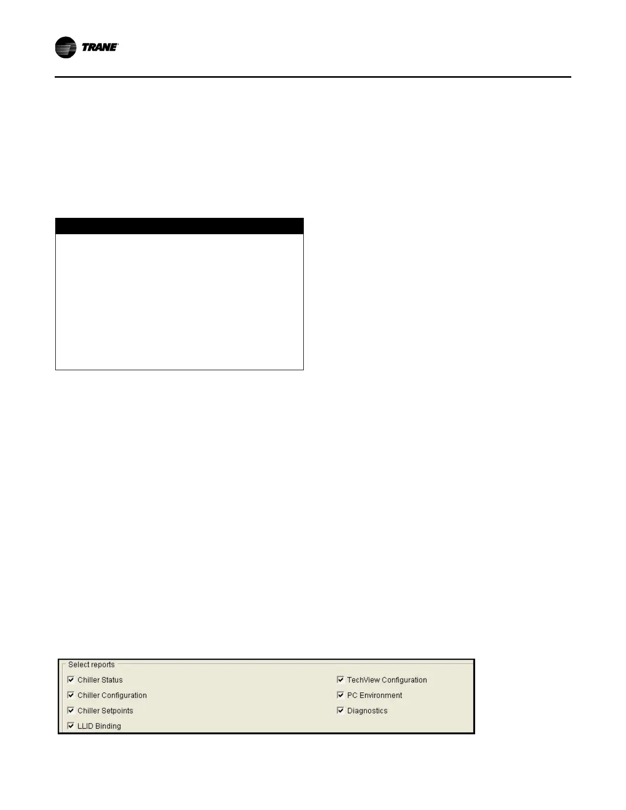
2. Select all reports to ensure a complete report and convert
the report to PDF. The PDF will be required to manually
copy configuration and setpoint values with Tracer
®
TU
after the Tracer AdaptiView™ display and UC800 are
installed.
3. Verify that the PDF was printed. The PDF will be used
when configuring the upgraded UC800 controller within
Tracer TU.
After the configurations and settings from the CH530
DynaView controller have been saved to a file on your service
computer, the controller change-out can proceed.
NOTICE
Excessive Cable Lengths Between AFDR
Drive and Compressor Motor!
Trane assumes no responsibility for equipment
damage caused by use of improper cable lengths. The
variable frequency drive industry recommends that the
length of the electrical cables connecting a drive unit to
a motor should be kept to less than 250 feet to protect
the motor from reflected voltage waves that can cause
the motor to fail. Cable lengths that exceed 250 feet
between the drive and the motor create the potential for
damage to occur to the motor windings and/or
insulation.
Figure 17. Select reports