Installation
SO-SVN048A-EN 49
Dual Relay Output 1A8 Connections
7. Using 16 AWG wire, make the following connections listed
in Table 13.
AFD Control Wire Connections
8. Using 16 AWG wire make the following connections to the
AFD listed in Table 14.
Important:
• Remove and discard white wire connecting Pin 12 and Pin
37 on the AFD drive.
• The red wire needs to be removed from the connector on
the UC800 end.
• The red wire on the Modbus
®
cable is NOT connected to
the AFD.
Table 12. Pin-out, relay 1K15
Terminal—
Relay 1K15 Description Mating Connection Description
10 N/C contact 1X5-4 thru 7 115V “hot”
11 N/O contact 1X5-4 thru 7 115V “hot”
2 N/C contact 1X5-1
Heaters - 4E1,
4E2, Wires: 28A
and 28B
7 N/O contact 1X5-2
Primary Oil
Solenoid 4Y3 -
Wire: 29B
A2 Coil - com 1X5-8 thru 11 115V “common”
A1 Coil - “hot” Pin 5 - AFD Drive Running Relay
Table 13. Pin-out, dual relay output (1A8)
Terminals—
1A8 Description Mating Connection Description
J11 Pins 1–4 PWR/Com WB2
LLID
communication/
power bus
J2 Pin 6 Relay 115V in 1X5-4/7 To 115V “hot”
J2 Pin 4 Relay N/O 1X5-2
To Primary Oil
Solenoid 4Y3 -
Wire: (29B)
Table 14. Pin-out, AFD
Terminal—
AFD Description Mating Connection Description
Pin 61
Modbus
®
(RS485)
Com (BK)
PIN 2 (IMC) UC800
1A1
Modbus (RS485)
Com (BK)
Pin 68
Modbus (RS485) +
(BLU)
PIN 3 (IMC) UC800
1A1
Modbus (RS485) +
(BLU)
Pin 69
Modbus (RS485) –
(GY)
PIN 4 (IMC) UC800
1A1
Modbus (RS485) –
(GY)
Pin 4 Running Relay 1X5-4/7 115V “hot”
Pin 5 Running Relay 1K15, pin A1 Coil – “hot”
Pin 37 Safe Stop 1K14, pin 9 N/O contact
Pin 12 24V out 1K14, pin 5 N/O contact
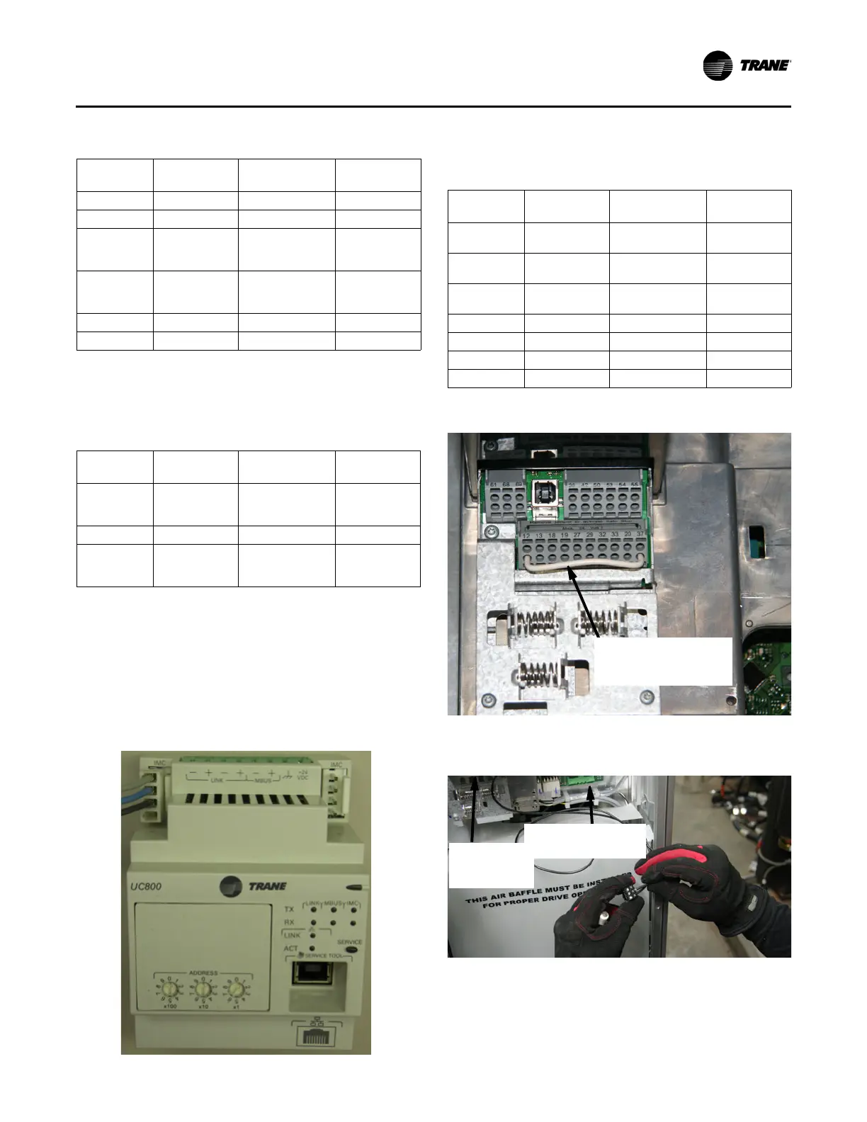
Figure 74. AFD—Remove white wire (safe stop)
Figure 75. AFD—Pin location safe stop and running
relay
Remove White Wire From
Pins 12 and 37 (Safe
Stop)
Pins 4 and 5
(Running Relay2)
Pins 12
and 37
(Safe Stop)