Installation
48 SO-SVN048A-EN
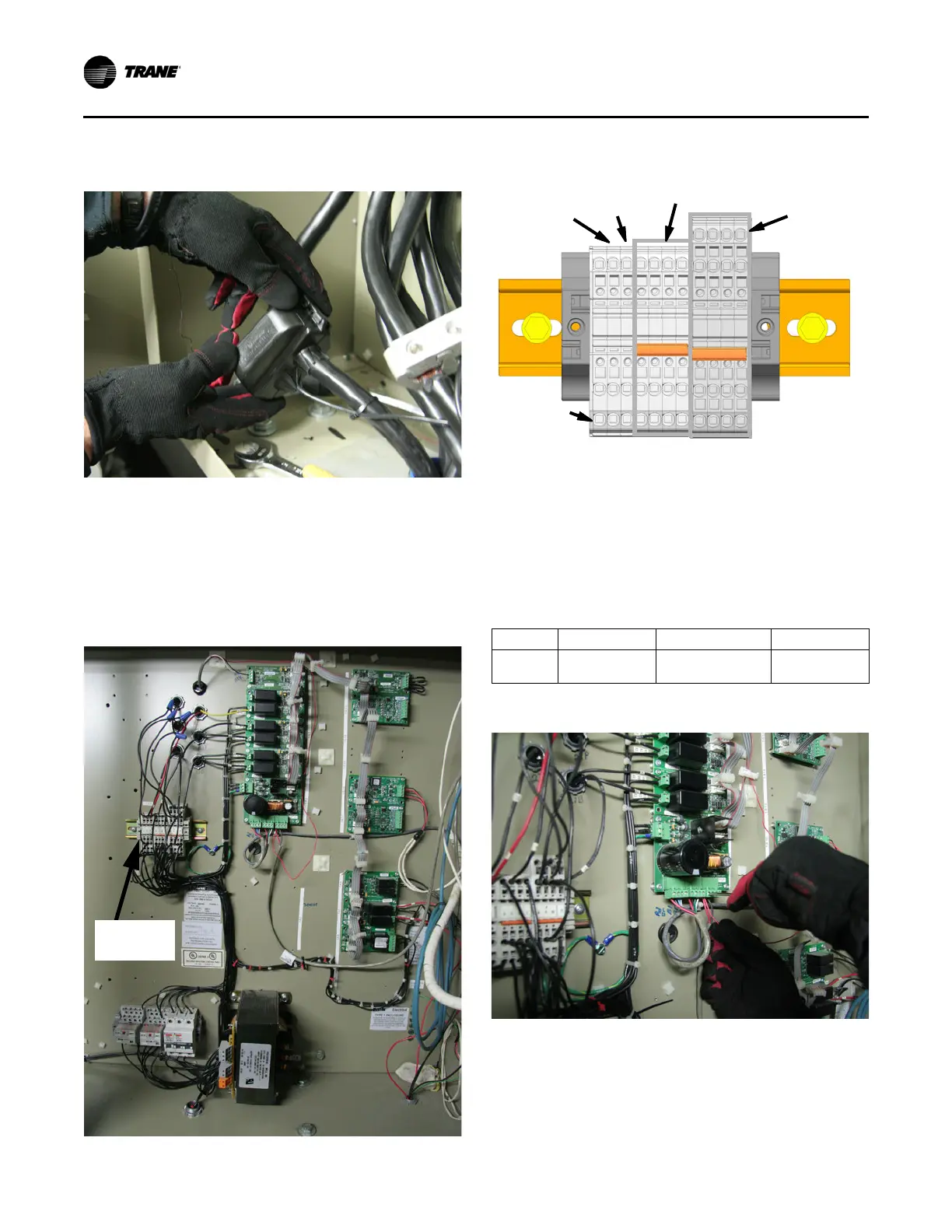
4. Install wire tap case; refer to Figure 70.
Note: The following connections will be connected to some
Terminal 1X5. Terminals 1X5-4 through 1X5-7 are
electrically tied together and are connected to terminal
X1 of the control power transformer (115V hot).
Terminals 1X5-8 through 1X5-11 are electrically tied
together and connect to terminal X2 of the control
power transformer, (115V com); refer to Figure 71.
Oil Loss Liquid Level Sensor Connections
5. Reconnect the oil loss liquid level sensor 24V supply to
power supply 1A2 connector J5, Pin 1; this is a red wire
(64A) and was previously connected to the starter module
J3 Pin 1.
Note: J3 or J4 Pin 1 on power supply 1A2 may also be
used for oil loss liquid level sensor connection.
1K15 Relay Connections
6. Using 16 AWG wire, make the following connections listed
in Tabl e 1 2.
Figure 70. Wire tap case install
Figure 71. 1X5 Terminal location
Figure 72. Terminals 1X5-1 through -11
Table 11. Pin-out, oil loss liquid level sensor (4B2)
Wire Description Mating Connection Description
64A (Red) Sensor 24v+ in
J5, Pin 1,
Power Supply (1A2)
24V+ out
Figure 73. Oil loss liquid level sensor connection
1234567 891011
1X5-2 Primary
Oil Sol (4Y3)/
Dual Relay (1A8)
1X5-3 HP
Cutout (4829)
Tied 1X5-4 through -7 Electrically Tied
(115V = “Hot”)
1X5-8 through -
11 Electrically
Tied (115V -
Com)
1X5-1 Heaters
(4E1, 4E2)