Installation
SO-SVN048A-EN 47
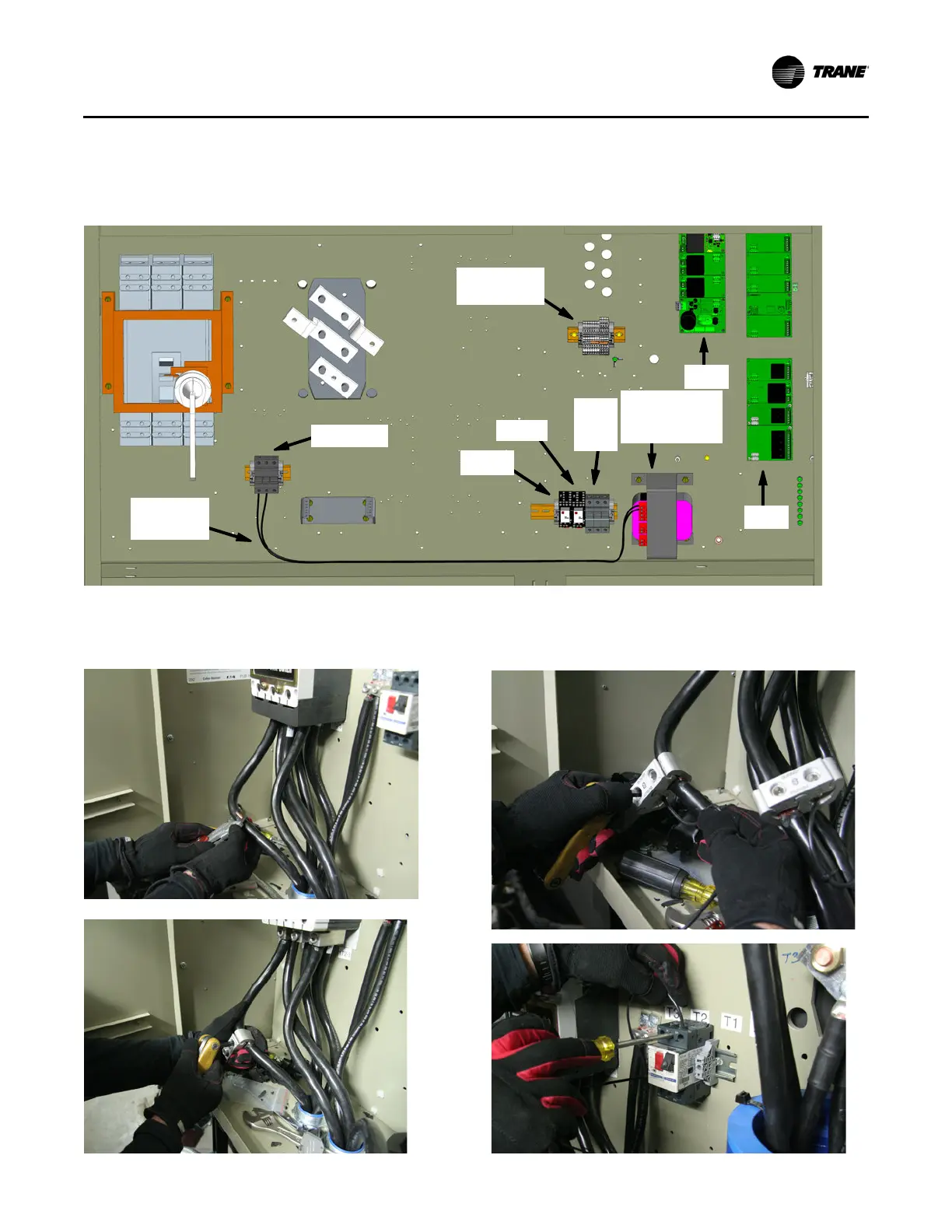
Panel Control Wiring
Refer to schematic 5071-1783 for the following connections.
1. Using the provided 12 AWG, route wires 20A, and 21A
from the 1F1 and 1F2 fuse to the control power wire
transformer, terminals H1 and H2; refer to Figure 67.
2. Strip insulation from Line 1 and Line 2 and install wire taps;
refer to Figure 68.
3. Connect one 12 AWG to the opposite side of each wire tap
and route wire to the 1F1 and 1F2 fuse; refer to Figure 69.
Figure 67.
Terminals
1X5-1/11
1A2
1A8
1K15
1K14
1F1, 1F2
Wires
20A, 21A
1F4,
1F5,
1F6
Control Power
Transformer
Approximate
of round
ugs
location
Figure 68. Wire tap installation Figure 69. 12 AWG wire connections