Installation
44 SO-SVN048A-EN
Line Voltage
AFD Mounting – Pedestal Installation
(All Kits)
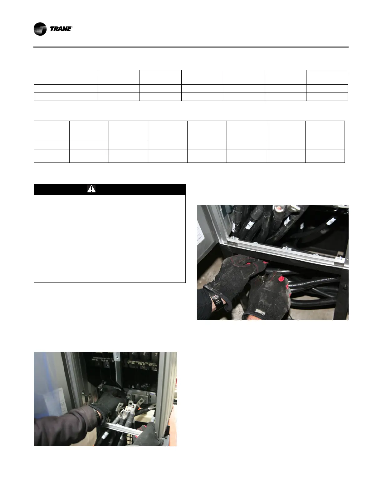
1. Remove the front cover of the pedestal base for easy
access to power wires Using safe lifting practices and
keeping the wires inside the drive enclosure, carefully
lower the drive onto the pedestal base.
2. After lowering the drive onto the pedestal, securely fasten
the drive to the base at all connection points at the front and
back of the base.
3. Connect all power wire and dedicated ground wire to the
drive according to the supplied schematics. AFD
termination location allows 2 wires per phase.
Table 9. AFDR unit weights and heat rejection (460V/480V)
460V/480V Catalog
Max Amps
158 Catalog/190
Maximum
200 Catalog/240
Maximum
252 Catalog/302
Maximum
301 Catalog/361
Maximum
369 Catalog/443
Maximum
446 Catalog/535
Maximum
Weight (lb) 135 135 135 275 275 275
Heat Rejection (BTU/hr) 7708 9286 12370 12161 15566 19477
Table 10. AFDR unit weights and heat rejection (575V/600V)
575V/600V
Catalog Max
Amps
109 Catalog/131
Maximum
129 Catalog/155
Maximum
160 Catalog/192
Maximum
202 Catalog/242
Maximum
242 Catalog/290
Maximum
287 Catalog/344
Maximum
333 Catalog/400
Maximum
Weight (lb) 135 135 135 275 275 275 275
Heat Rejection
(BTU/hr)
5939 7168 9037 10488 12701 15232 17154
WARNING
Hazardous Voltage w/Capacitors!
Failure to disconnect power and discharge capacitors
before servicing could result in death or serious injury.
Disconnect all electric power, including remote
disconnects and discharge all motor start/run
capacitors before servicing. Follow proper lockout/
tagout procedures to ensure the power cannot be
inadvertently energized. For variable frequency drives
or other energy storing components provided by Trane
or others, refer to the appropriate manufacturer’s
literature for allowable waiting periods for discharge of
capacitors. Verify with a CAT III or IV voltmeter rated per
NFPA 70E that all capacitors have discharged.
Figure 59.
Figure 60.