RLC-SVX19J_SHORT-GB
27
Operating Principles
This section describes the overall fl ow chart principle for RTAF. Detailed information for a given order is supplied with
order package documentation.
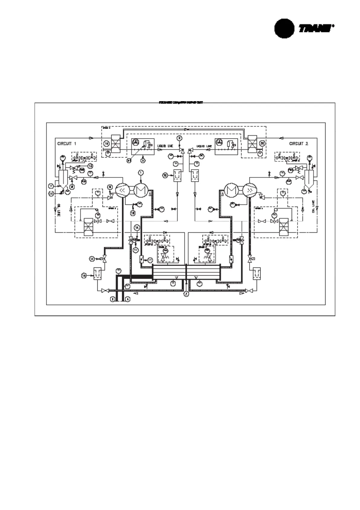
Figure 12 – Example of Typical Refrigerant System Schematic & Oil Lube Circuit Schematic
1 = Screw compressor
2 = Evaporator
3 = Air-cooled condenser
4 = Evaporator water inlet connection
5 = Evaporator water outlet connection
6 = Oil service valve
7 = Oil separator
8 = Discharge service valve
9 = Liquid shut off valve
10 = Filter drier
11 = Electronic expansion valve
12 = Sight glass
13 = Relief valve
14 = Service valve
15 = Oil line solenoid valve
16 = Oil fi lter
17 = Suction service valve
18 = Schraeder valve
19 = PHR water inlet connection
20 = PHR water outlet connection
21 = Refrigerant tank
PT = Pressure transducer
PSH = High pressure relief valve
PSL = Low pressure relief valve
PZH = High pressure switch
TT = Temperature sensor
TCE = Electronic expansion valve
TC = Expansion valve
OS = Optical sensor
Option A = Auxilliary oil cooler
Option B = Dual Relief Valve
Option C = Heat Recovery
Option D = Refrigerant tank according the unit size and
the unit version