RLC-SVX19J_SHORT-GB
5
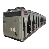
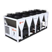
Digit 1, 2, 3, 4 – Unit model
RTAF = Air-Cooled Chiller
Digit 5 to 7 - Nominal Tonnage
090 = 90 tons
100 = 100 tons
101 = 101 tons Brine application - 2 compressors
105 = 105 tons
110 = 110 tons
120 = 120 tons
125 = 125 tons
130 = 130 tons
140 = 140 tons
141 = 141 tons Brine application - 3 compressors
145 = 145 tons
150 = 150 tons
155 = 155 tons
165 = 165 tons
170 = 170 tons
175 = 175 tons
185 = 185 tons
190 = 190 tons
191 = 191 tons Brine application - 4 compressors
200 = 200 tons
205 = 205 tons
210 = 210 tons
225 = 225 tons
230 = 230 tons
245 = 245 tons
250 = 250 tons
265 = 265 tons
275 = 275 tons
280 = 280 tons
285 = 285 tons
300 = 300 tons
305 = 305 tons
310 = 310 tons
330 = 330 tons
340 = 340 tons
350 = 350 tons
355 = 355 tons
370 = 370 tons
380 = 380 tons
400 = 400 tons
405 = 405 tons
410 = 410 tons
415 = 415 tons
450 = 450 tons
470 = 470 tons
510 = 510 tons
550 = 550 tons
Digit 8 – Unit voltage
D = 400V/50Hz/3ph
4 = 460V/60Hz/3ph
J = 380V/60Hz/3ph
Digit 9 – Manufacturing Location
E = Europe
Digit 10, 11 – Design sequence
A0 = Factory assigned
Digit 12 - Effi ciency
N = Standard Effi ciency
H = High Effi ciency
A = Extra Effi ciency
U = High Seasonal Short (HSS)
V = High Seasonal Effi ciency
B = Extra Seasonal Effi ciency (XSE)
C = Extra Seasonal Short (XSS)
Digit 13 – Agency listing
C = CE Marking
Digit 14 – Pressure vessel code
2 = PED (Pressure equipment directive)
D = Australian code
Digit 15 – Acoustic level
X = Standard noise (SN)
L = Low noise (LN)
A = AC Extra Low Noise
Q = Low Noise with Night Noise SetBack (NNSB)
E = Extra Low Noise (XLN)
W = Whisper Low noise (WLN)
Digit 16 – Operating map : airside
X = Standard ambient
L = Low ambient
H = High ambient
Digit 17 – Relief valve option
L = Single Relief Valve High Pressure side
D = Dual Relief Valve with 3 way valve High Pressure side
Digit 18 – Water connection
X = Grooved pipe connection
W = Grooved pipe with coupling and pipe stub
Digit 19 – Operating map water side
N = Comfort cooling (above 4.4°C)
P = Process cooling (below 4.4°C) (Brine application)
C = Ice Making (-7°C to 20°C)
Digit 20 – Evaporator Confi gurations
2 = Standard pass evaporator
T = Standard Pass Evaporator + Turbulators
Digit 21 – Thermal Insulation
N = Standard
H = High performance
X = None
Digit 22 – Condenser Coating
N = Aluminum Micro Channel
C = E-Coated Micro Channel (Free Cooling excluded)
Digit 23 - Heat Recovery
X = No Heat Recovery
P = Partial Heat Recovery
Q = Partial Heat Recovery with on site fan control (PHR +)
T = Total Heat Recovery (full equipment)
V = Total Heat Recovery (no piping connection)
Digit 24 – Hydraulic module
X = Pump signal On/Off
1 = Dual pump standard pressure
3 = Dual pump high pressure
Unit Model Number Description