12 CVRF-SVN005C-EN
Installation
Control Panel Conversion
The control panel conversion will consist of removing, marking,
and retaining selected wires in the existing control panel. The
existing control panel will be removed.
The new control panel will be installed. The existing wires will
be terminated
on the terminal block or LLIDs in the control
panel along with any new wires required.
Make a note of run hours and starts o
n the hour meter and start
counter. Symbio™ controller will allow you to enter this
information into its program.
Remove the nameplate from the exi
sting panel. If the chiller
original nameplate is a stick-on label, it may be necessary to
cut out the metal section. This nameplate needs to be moved
and attached to the new control panel near the new control
panel nameplate. The old nameplate contains original unit
information that will be useful in service and parts issues in the
future.
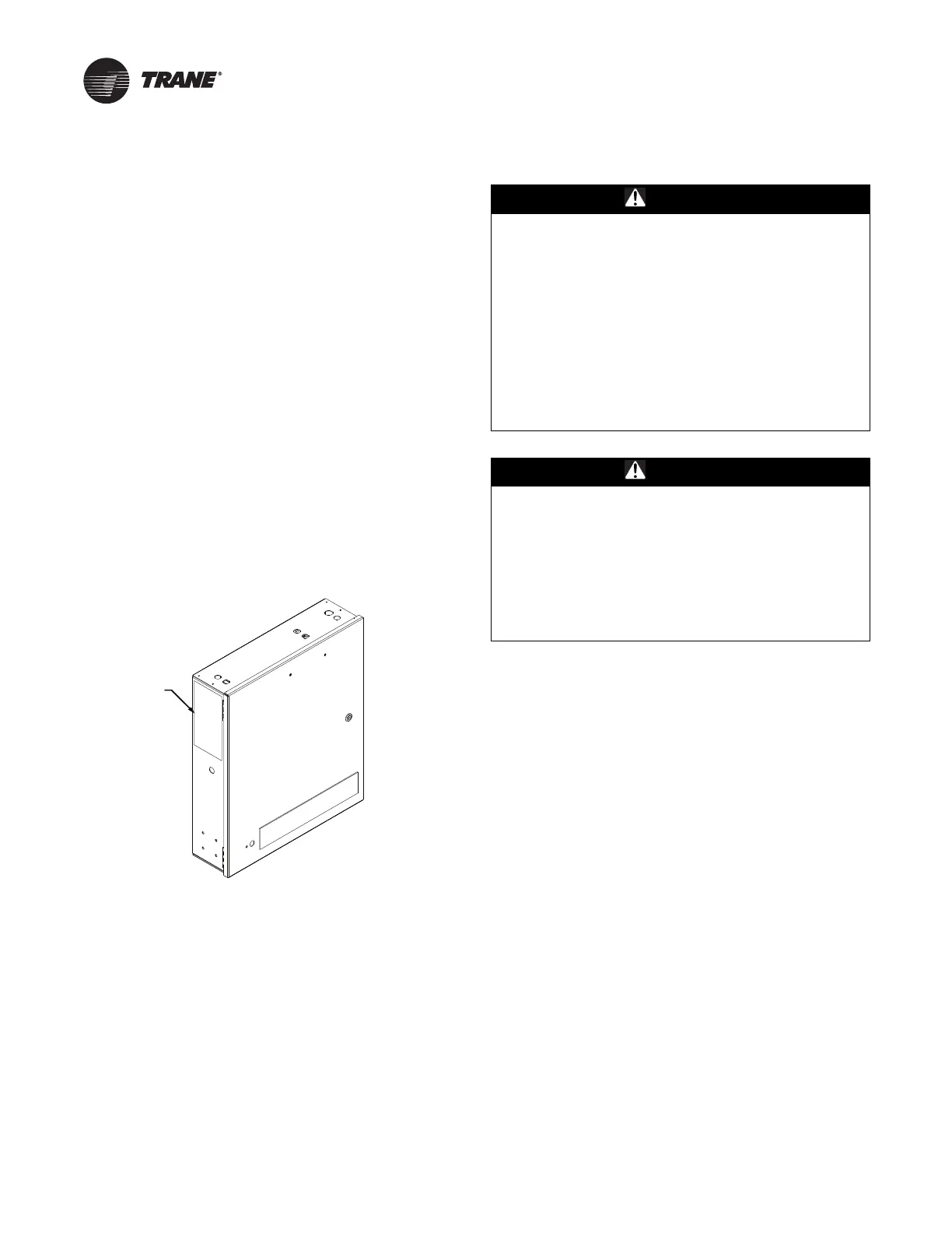
A blank vinyl nameplate is included. Transfer information from
th
e old nameplate to the new one and install on new panel.
Figure 2. Recommended nameplate location on new
pa
nel
Before You Begin
1. Identify all field modifications made to the existing chiller
control scheme; then label all field-installed wiring entering
the control panel accordingly, if required. This may include
things like the power supply for the purge and any BAS
interface wiring.
2. Determine how each of the field-adapted control functions
just iden
tified in Step 1 will be assumed by the new
Symbio™ chiller control panel.
3. Capture all existing chiller control settings before powering
dow
n chiller controls.
4. Open all starter and control panel disconnect switches and
secure them in th
at position.
WARNING
Hazardous Voltage w/Capacitors!
Failure to disconnect power and discharge capacitors
before servicing could result in death or serious injury.
Disconnect all electric power, including remote
disconnects and discharge all motor start/run
capacitors before servicing. Follow proper lockout/
tagout procedures to ensure the power cannot be
inadvertently energized. For variable frequency drives
or other energy storing components provided by Trane
or others, refer to the appropriate manufacturer’s
literature for allowable waiting periods for discharge of
capacitors. Verify with a CAT III or IV voltmeter rated per
NFPA 70E that all capacitors have discharged.
WARNING
PPE for Arc/Flash Required!
Failure to wear appropriate PPE could result in death or
serious injury.
On this unit, if the handle shield is cracked the circuit
breaker could arc/flash when reset. To avoid being
injured, technicians MUST put on all necessary
Personal Protective Equipment (PPE), in accordance
with NFPA70E for arc/flash protection, PRIOR to
entering the starter panel cabinet.
Note: T
o eliminate migration of refrigerant into the oil
sump, temporarily connect a field supplied
thermostat and an auxiliary 115 Vac power source
to the oil heater. Refer to wire 42A on the IU2
module, terminal J20-I.
5. Disconnect all field-installed wiri
ng entering the control
panel (i.e., identified in Step 1) from the control panel
termina
l strip. This is typically between 1TB1-10 to -12 and
1TB1-11 to -13.
6. Remove from the control panel terminal block all wiring that
h
as been routed through conduit from the starter panel to
the control panel. (Wires 3D, 4C and oil pump interlock
between 1TB1-7 to -8 and 120 Vac power to control panel
between 1TB1-1 to -2 are typical.)
 Loading...