32
18-GJ89D1-1F-EN
Electrical — Low Voltage
TAMX can be used in either Link Communicating mode
or 24 volt mode. In Link Communicating mode, all
configurations are made by using the configuration
menu in the User Interface (UX360) or from the
Diagnostic Mobile App. In 24 volt mode, basic
operation is configured from the factory with no
defaults for accessories. All configurations for blower
delays, accessories etc., need accomplished using the
Diagnostic Mobile App.
Table 16. Low Voltage Maximum Wire Length
The Low Voltage Maximum Wire Length table
defines the size and combined total maximum
length of the low voltage wiring from the
outdoor unit, to the indoor unit, and to the
thermostat.
Note: The use of color coded low voltage wire
is recommended to simplify
connections between the outdoor unit,
the control, and the indoor unit.
Control Wire — Communicating
WIRE SIZE MAX. WIRE LENGTH
18 AWG 500 FT. Combined
Control Wire — 24 Volt
WIRE SIZE MAX. WIRE LENGTH
18 AWG 100 FT. Combined
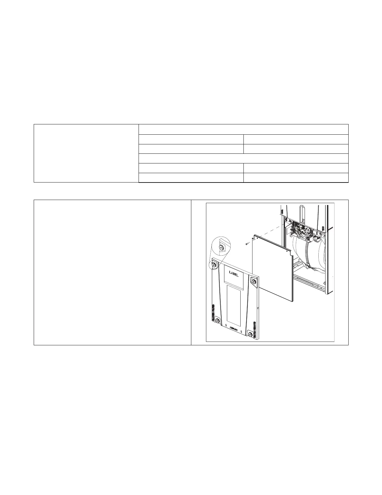
Table 17. Low Voltage Hook-up Instructions
1. Remove the Blower panels by removing the four fasteners and
then pulling away from the cabinet to remove.
2. Remove the block off plate by removing the two 5/16” screws at
the top and pulling the top out and up off the support bosses at
the bottom.