34
18-GJ89D1-1F-EN
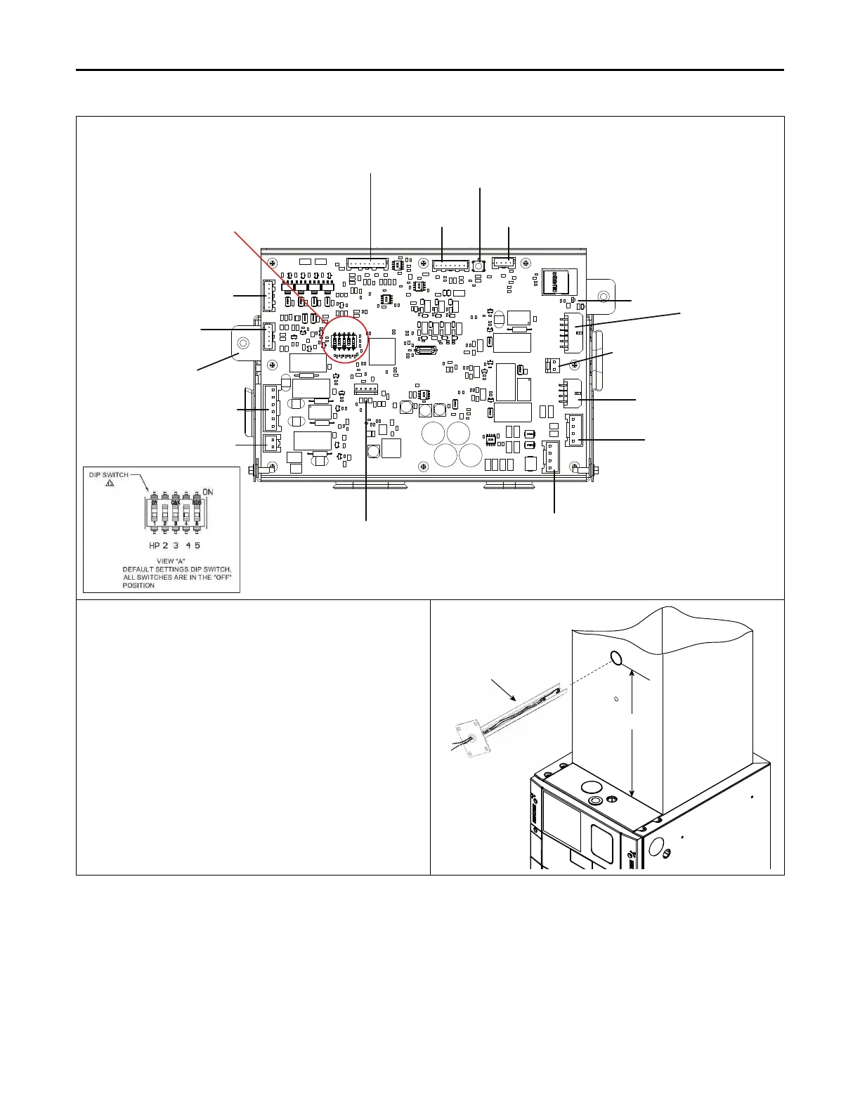
6. Secure the sheathed wiring to the control pocket mounting plate using the factory supplied wire ties attached to the tabs as shown.
AHC
J8 24 Volt Input
S2
J10
Electric HT
J7 Motor
BOX
J1 EEV
Dip switch is rotated
upside down in unit
View A
J3 Sensors
J2 CAN
Connector
J5 CAN Connector
J14 External Switches
and
Humidifier
J15 24 volt low
voltage harness
J11 Supply Air
Temperature Sensor (SAT)
LED
J13 Sensors
S1 BLE
Button
J12
7. Mount Supply Air Temperature Sensor
The Supply Air Temperature (SAT) Sensor must be mounted a
minimum of 8” above the edge of the supply duct (additional distance
is preferred when possible). Locate the SAT Sensor in an area of the
discharge air duct where less air turbulence is expected. Avoid dead
air areas where representative discharge air temperatures may not
exist.
The plug on the SAT Sensor harness plugs directly onto the AHC
Board. Refer to the figure in Step 7, Table 14.
Note: Supply Air Temp Sensor (SAT) is used in Link Communicating
mode and is optional in 24 volt mode.
Note: Supply Air Temp Sensor (SAT) ships with SC360 System
Controller.
Note: Supply Air Sensor kit is BAYSENSC360.
Supply Air
Temperature
Sensor
8” Min.
EElleeccttrriiccaall —— LLooww VVoollttaaggee