TK 55676-19-IM-EN
47
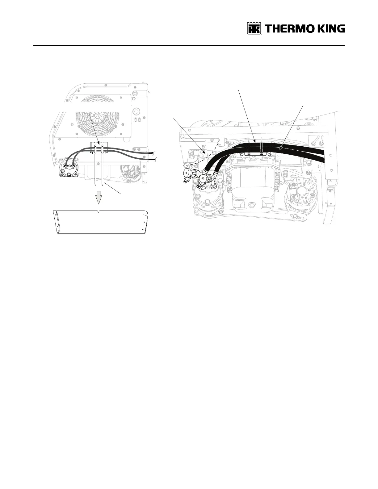
Figure 25. Suction and Discharge Hoses Shown Correctly Routed and Secured
RCS1632
Hoses shown correctly routed and secured
with bandwraps to hose support bracket.
DISCHARGE HOSE ON TOP
SUCTION HOSE ON BOTTOM
Remove excess length
after tightening
Remove bottom panel
Underside of APU showing hoses correctly routed and
secured with bandwraps to the hose support bracket
IMPORTANT: Keep hoses away from
fuel strainer, fuel fittings, and bracket
CCoommpprreessssoorr ttoo EEvvaappoorraattoorr
6. From the APU, route the ##1100 ssuuccttiioonn hhoossee up through the 3” access hole in the tractor floor to the evaporator:
a. Cut the hose to the appropriate length, attach a ##1100 ffiittttiinngg and connect to the #10 suction fitting on the
evaporator
AAPPUU ttoo CCoonnddeennsseerr
7. From the APU, route the ##88 ddiisscchhaarrggee hhoossee to the condenser coil:
a. Cut the hose to the appropriate length, attach a ##88 ffiittttiinngg and connect to the #8 discharge fitting located near the
top of the condenser coil.
EEvvaappoorraattoorr ttoo RReecceeiivveerr DDrriieerr
8. Fabricate a ##66 hhoossee and fitting and attach onto the ##66 lliiqquuiidd lliinnee ffiittttiinngg on the evaporator:
a. Route the hose down through the 3” access hole in the tractor floor to the receiver drier.
b. Cut the hose to the appropriate length, attach a ##66 ffiittttiinngg and connect to the OOUUTTLLEETT end indicated by arrow on
the receiver drier.
CCoonnddeennsseerr ttoo RReecceeiivveerr DDrriieerr
9. Fabricate a ##66 hhoossee and fitting and attach onto the ##66 ffiittttiinngg on the condenser coil:
a. Route the hose to the receiver drier.
b. Cut the hose to the appropriate length, attach a ##66 ffiittttiinngg and connect to the IINNLLEETT end on the receiver drier.
10. Tighten all fittings as specified in the chart.
11. Reinstall and secure APU side panel.
NNoottee:: The bottom pan will be reinstalled in a later step.
AA//CC HHoossee IInnssttaallllaattiioonn