DX cooling operation
CNT-SVX05B-EN 67
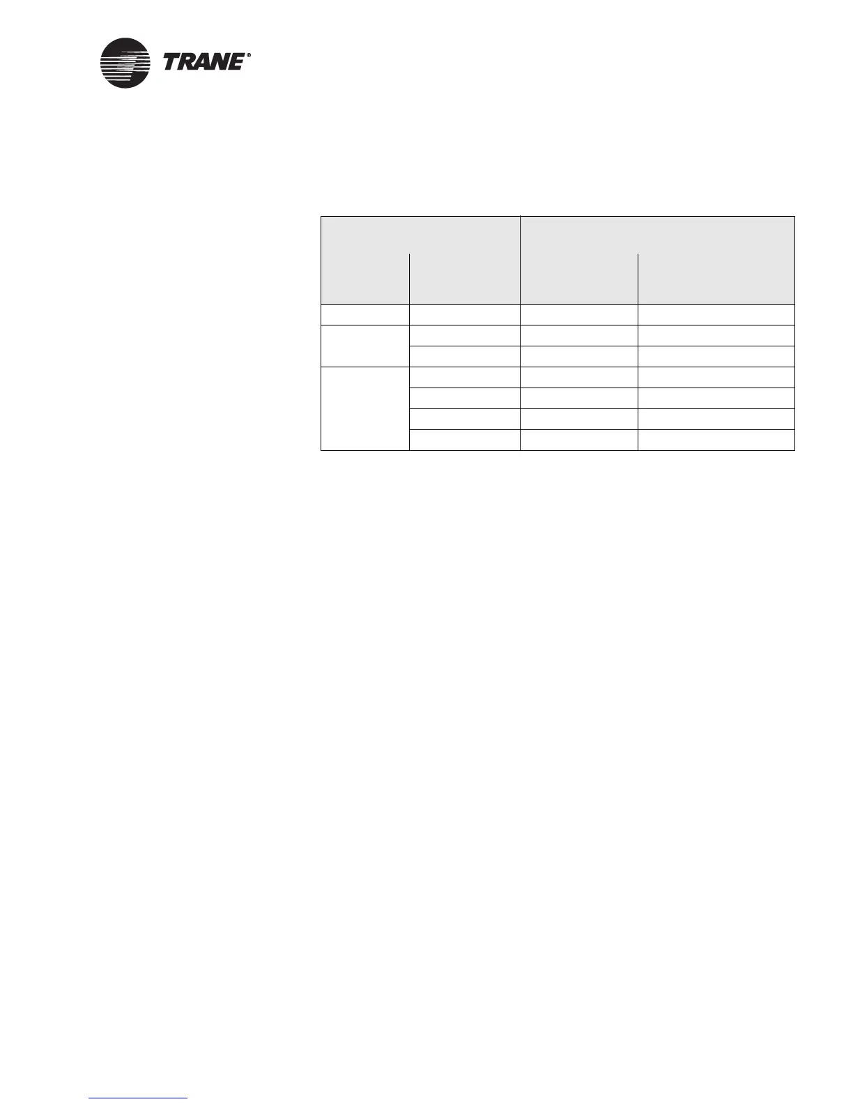
circuit 1, and, finally, BO6 to the second stage of circuit 2 (see Table 26 on
page 67).
Frost protection
The controller provides three options for coil frost protection. Use the
Rover service tool to properly configure the controller for the following
options.
• Analog thermistor input (evaporator refrigerant temperature sensor)
wired to the universal analog input (IN13).
• Binary thermostat device wired to binary input IN7, coil defrost
input.
• Binary thermostat device wired to binary input IN12, coil defrost
input.
Two-circuit split-system DX cooling applications should apply an evapo-
rator refrigerant sensor or binary thermostat device on the first circuit or
the circuit of the first cooling stage.
For protection on each circuit both an evaporator refrigerant sensor and
binary thermostat sensor or two binary thermostat sensors can be used at
the same time. Apply a sensor to each circuit. The controller will respond
according to the active input.
Also two binary thermostat devices can be applied to each circuit and
wired in series to binary input IN7 or IN12. If either device detects a low
refrigerant temperature condition, the controller will enter a defrost
mode of operation.
Minimum On and Off timers
Remove (if installed), or disable, all electromechanical compressor mini-
mum On and Off timers from the condensing unit. The controller will
enforce a minimum On time and minimum Off time for each compressor
stage. A compressor will not be allowed to stage On until the compressor
minimum Off time has expired, and a compressor will not be allowed to
Table 26. DX cooling compressor circuit wiring
Tracer AH540/541 controller Condensing unit
DX cooling
stages
Binary output Single circuit Two circuit
1 BO3 1st stage N/A
2 BO3 1st stage 1st stage of circuit 1
BO4 2nd stage 1st stage of circuit 2
4 BO3 1st stage 1st stage of circuit 1
BO4 2nd stage 1st stage of circuit 2
BO5 3rd stage 2nd stage of circuit 1
BO6 4th stage 2nd stage of circuit 2
 Loading...


